Electrical acoustic converter

a technology of electrical acoustic converter and converter, which is applied in the direction of transducer details, instruments, electrical transducers, etc., can solve the problems that compact and thin electrical acoustic converters cannot be obtained

Inactive Publication Date: 2006-03-07
CITIZEN ELECTRONICS CO LTD
View PDF3 Cites 4 Cited by
  • Summary
  • Abstract
  • Description
  • Claims
  • Application Information

AI Technical Summary

Benefits of technology

[0016]The present invention is made in view of the problem in the conventional electrical acoustic converter, and it is, therefore, an object of the present invention to provide a compact and thinned electrical acoustic converter.

Problems solved by technology

However, there is a problem in the above conventional acoustic converter that a compact and thinned electrical acoustic converter cannot be obtained because the coil contact springs are disposed outside the outer peripheral edge of the diaphragm, and furthermore because the terminals of the coil contact springs are extended perpendicularly.

Method used


Image

  • Electrical acoustic converter
  • Electrical acoustic converter
  • Electrical acoustic converter

Examples


Embodiment Construction

[0028]Some embodiments of the present invention will be explained with reference to the accompanying drawings below.

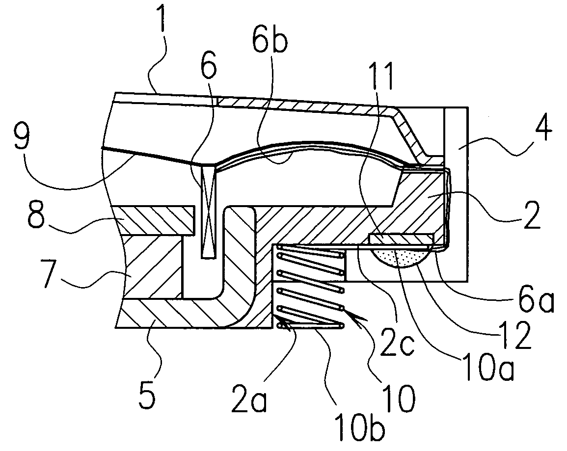
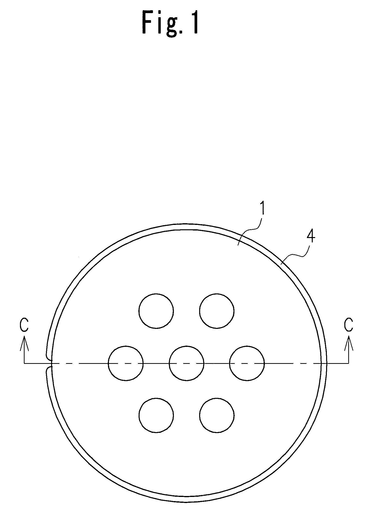
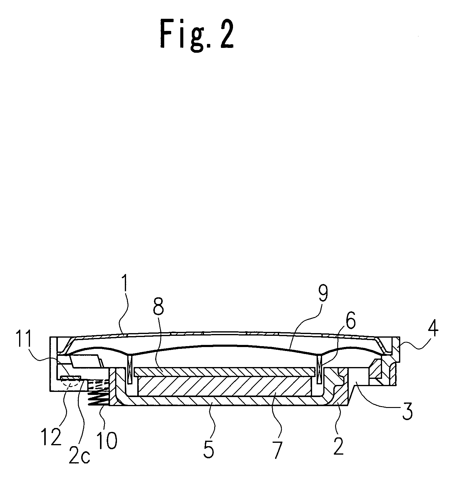
[0029]Referring to FIGS. 1 to 4, an electrical acoustic converter according to the present invention is illustrated. The electrical acoustic converter comprises a body part including a base cover 2 and a top cover 1 attached through a frame 4 to the base cover 2.

[0030]Disposed within a space formed between the top cover 1 and base cover 2 is an electromagnetic sound generating part which has a diaphragm 9 attached to the base cover 2 and a drive part causing the diaphragm 9 to vibrate, for example. The drive part includes a yoke 5 fitted to the base cover 2, a magnet 7 mounted on the yoke 5, a top plate 8 mounted on the magnet 7 and an exciting coil 6 disposed to oppose side surfaces of the magnet 7 and top plate 8.

[0031]Here, an upper end, for example, of the exciting coil 6 is attached to the diaphragm 9, as shown in FIGS. 2 and 4. When the exciting coil 6 is dispose...


PUM


Abstract

Disposed within a space formed between a base cover (2) and a top cover (1) attached to the base cover (2) is an electromagnetic sound generating part which has a diaphragm (9) attached to the base cover (2) and a drive part causing the diaphragm (9) to vibrate. The drive part includes a yoke (5) fitted in the base cover (2), a magnet (7) mounted on the yoke (5), a top plate (8) mounted on the magnet (7) and an exciting coil (6) disposed to oppose to side surfaces of the magnet (7) and top plate (8). Coil contact springs (10) are contained into housings (2a) provided on portions of the base cover inside than an outer peripheral edge of the diaphragm. The coil contact springs (10) act to connect the exciting coil (6) with an outside power source. The base cover (2) is provided with a pair of connecting pieces (11) or lead frames which are used to connect the exciting coil (6) and coil contact springs (10). The connecting pieces (11) are embedded in the base cover (2).

Description

BACKGROUND OF THE INVENTION[0001]1. Field of the Invention[0002]The present invention relates to an electrical acoustic converter for generating a sound by vibrating a diaphragm by an electromagnet, more particularly, to a compact and thin-shaped electrical acoustic converter suitable for being mounted on a printed-circuit board or the like.[0003]2. Description of the Prior Art[0004]Recently, an electromagnetic sounder or electrical acoustic converter of a surface-mounted type, such as a miniature buzzer mounted directly on a printed-circuit board, becomes mainstream pursuant to increment of a surface-mounted technology of miniature electronic parts.[0005]Therefore, a great number of electrical acoustic converters are used in a field of conductive-type speakers and multiple function-type speakers assembled in a mobile communication device such as a cellular phone.[0006]A conventional electromagnetic sounder has coil contact springs provided outside an outer peripheral edge of a diap...

Claims


Application Information

Patent Timeline
Patent Type & Authority Patents(United States)
IPC IPC(8): H04R25/00H04R9/02G10K9/13H04R9/06H04R11/14
CPCH04R9/06
Inventor KUWABARA, ATSUSHIYONEYAMA, AKIRAOHTA, YOSHIZUMIKOBAYASHI, TERUMI
Owner CITIZEN ELECTRONICS CO LTD
Why Eureka
Try Eureka