Optical disk drive

A technology of optical disc drive and optical disc, which is applied in the directions of instruments, recording information storage, etc., can solve the problems that the optical disc drive is difficult to adopt, the optical disc drive becomes larger, and the moving time of the tray 30 becomes longer, so as to reduce the loading and non-loading time and improve the operation Quickly and minimize the effect of the length in the front-back direction

Inactive Publication Date: 2008-07-02
LEJIN GUANGDIAN ELECTRONIC CO LTD SHANGHAI
View PDF0 Cites 3 Cited by
  • Summary
  • Abstract
  • Description
  • Claims
  • Application Information

AI Technical Summary

Problems solved by technology

As a result the optical drive becomes larger overall
[0016] In particular, as mentioned above, since the front-rear length of the tray 30 is relatively long, the front-rear length of the optical disc drive itself is relatively large compared with the left-right width. Issues adopted in
[0017] In addition, in the above-mentioned conventional structure, the rack 33 is formed by extending from the front end to the rear end of the tray 30, so there is a problem that the moving time of the tray 30 becomes longer in order to replace the optical disc.

Method used


Image

  • Optical disk drive
  • Optical disk drive
  • Optical disk drive

Examples


Embodiment Construction

[0060] Hereinafter, specific embodiments of the optical disk drive of the present invention will be described in detail with reference to the accompanying drawings.

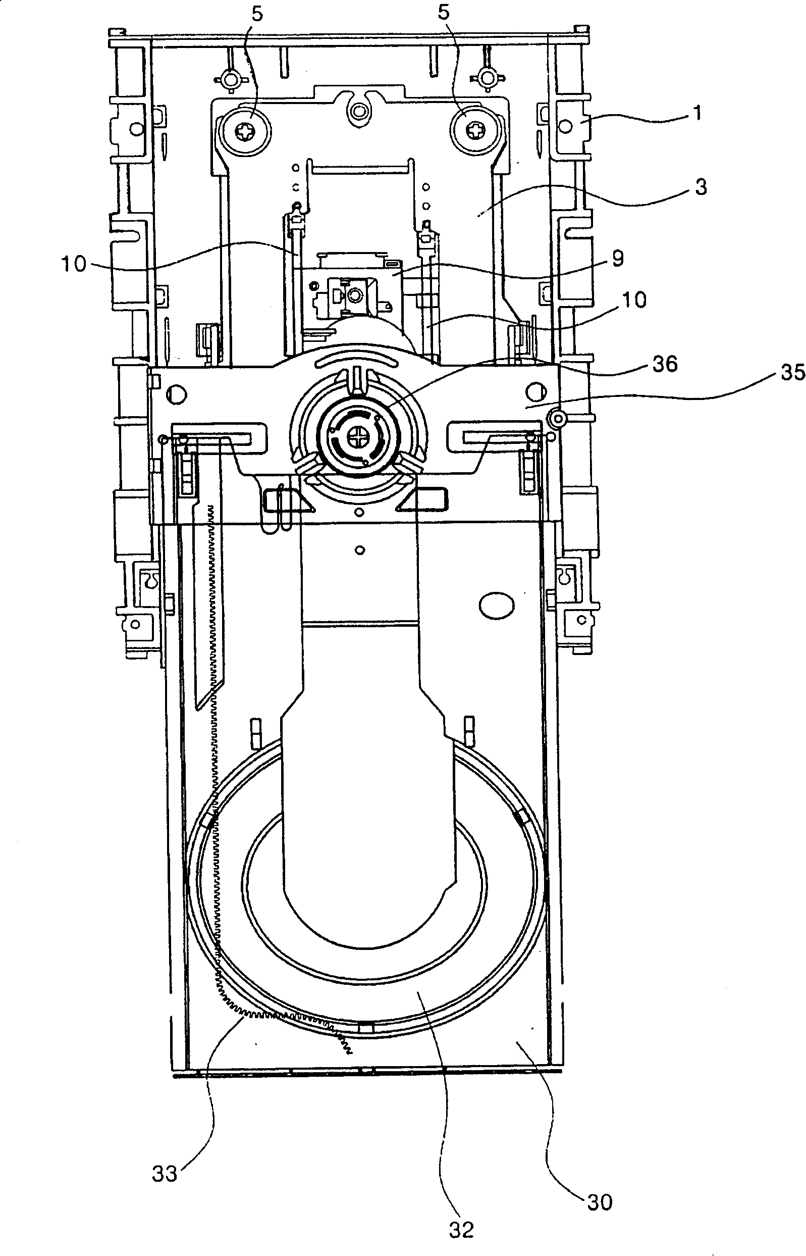
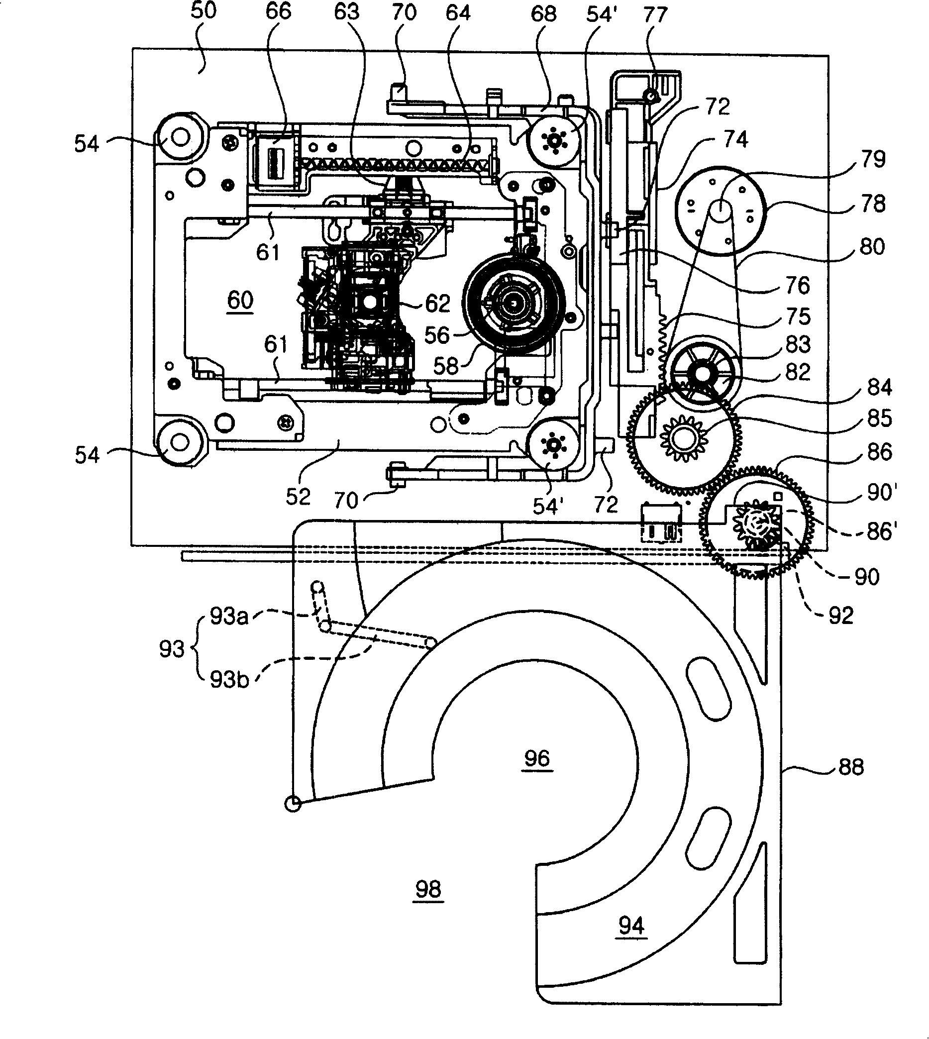
[0061] image 3 The configuration of the optical disc drive according to the present invention is shown schematically in plan. Figure 4 The structure of the pallet which constitutes the example of this invention is shown schematically in plan.

[0062] As shown in the drawings, the main base 50 forms the skeleton of the optical disc drive, and is a part for mounting various components constituting the optical disc drive. In the present invention, the above-mentioned main base 50 is a quadrilateral when viewed in a schematic plan view, and the front-to-back width is relatively shorter than the left-to-right width. The above-mentioned main base 50 surrounds the remaining part except the front part of the optical disk drive according to a case (not shown).

[0063] An optical pickup base 52 is provided on the ab...


PUM


Abstract

The invention relates to a compact disc driver, which comprises a main base, a light picker for allowing the front end of the main base to move left and right, a light picker base with a rotary plate for revolving the compact disc, wherein the light picker base is arranged on one side of the main base to allow itself to rotate, and a tray which loads and unloads the compact disc while moving according to the rotation toward inside and outside of the main base, and a loading electric motor which is arranged on the main base and allows the tray to rotate and the end of the light picker base with the rotary plate to ascend or descend. Compared with the amplitude of the main base in the front and back, the amplitude of the main base on the left and right is larger. The compact disc driver of the invention can minimize the length in the front and back and can be applicable to thin and small electronic products such that the loading time and unloading time of the compact disc are correspondingly reduced.

Description

technical field [0001] The present invention relates to an optical disc drive, and more particularly relates to an optical disc drive which records signals on the signal recording surface of the optical disc or reads the recorded signals while the optical disc is being rotated. Background technique [0002] figure 1 A schematic plan view illustrating the composition of important parts of an optical disc drive according to the prior art, [0003] figure 2 As a schematic diagram of the figure 1 The optical drive has a tray and clamp state in the main base. [0004] According to the illustration, the main base 1 forms the skeleton of the optical disc drive. An optical pickup base 3 is provided at the center of the above-mentioned main base 1 . The rear end portion of the optical pickup base 3 is held in a state of being sandwiched by the shockproof area 5 between the main base 1 . [0005] A spindle motor 7 for rotating an optical disc is provided in the above-mentioned ...

Claims


Application Information

Patent Timeline
Patent Type & Authority Applications(China)
IPC IPC(8): G11B17/054G11B17/04
Inventor 安永模
Owner LEJIN GUANGDIAN ELECTRONIC CO LTD SHANGHAI
Why Eureka
Try Eureka