Optical connector with sloped surface

a technology of optical connectors and sloped surfaces, applied in the field of optical connectors, can solve the problems of complex and difficult process of accurately aligning the reflective mirror with the photoelectric conversion chip

Inactive Publication Date: 2015-01-27
HON HAI PRECISION IND CO LTD
View PDF19 Cites 23 Cited by
  • Summary
  • Abstract
  • Description
  • Claims
  • Application Information

AI Technical Summary

Problems solved by technology

However, the essential step of accurately aligning the reflective mirror with the photoelectric conversion chip is a complex and difficult process.

Method used


Image

  • Optical connector with sloped surface
  • Optical connector with sloped surface
  • Optical connector with sloped surface

Examples


Embodiment Construction

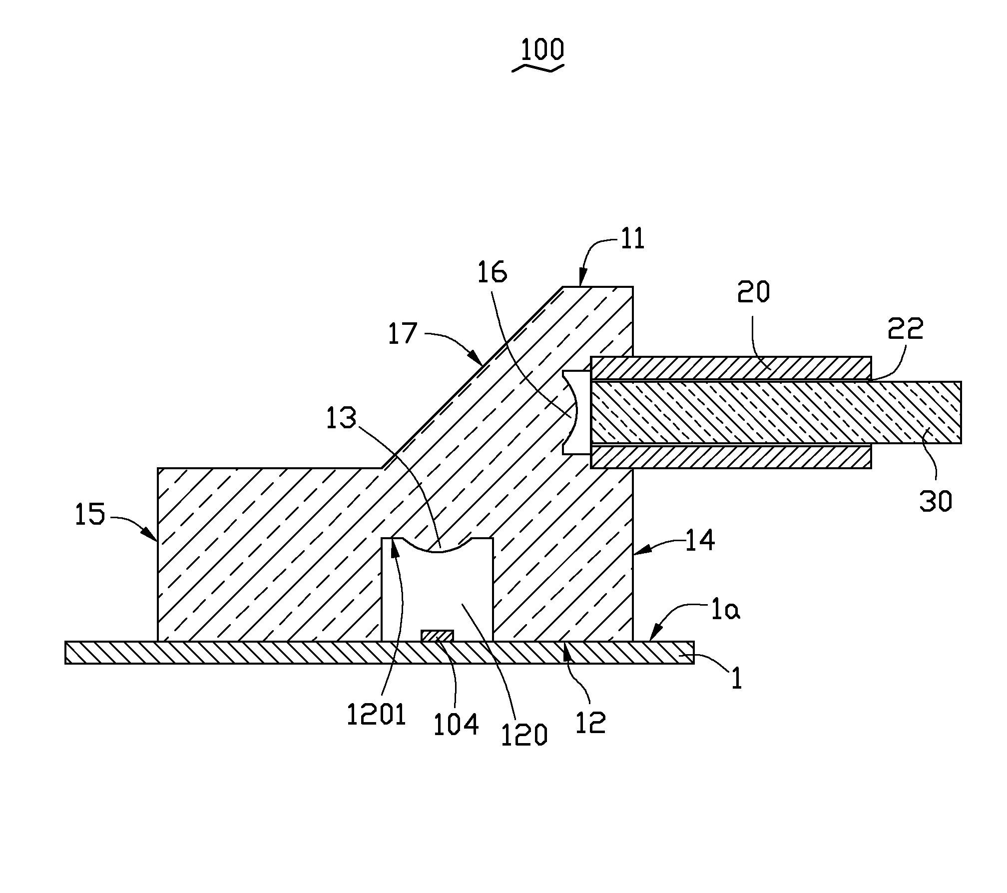
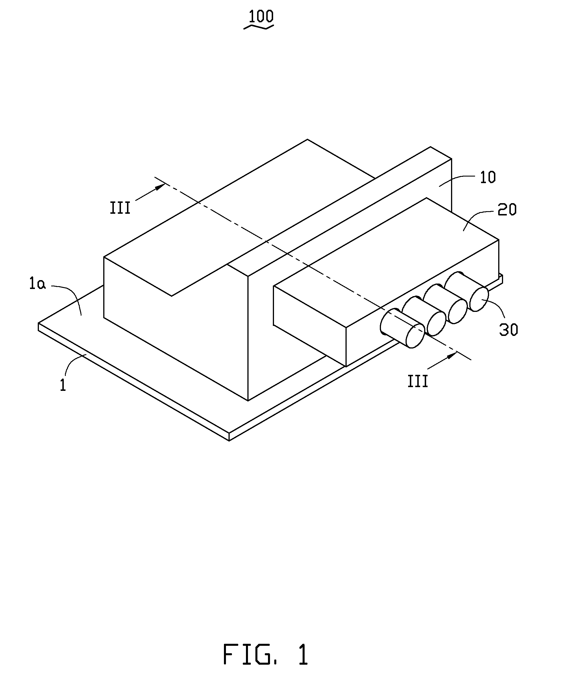
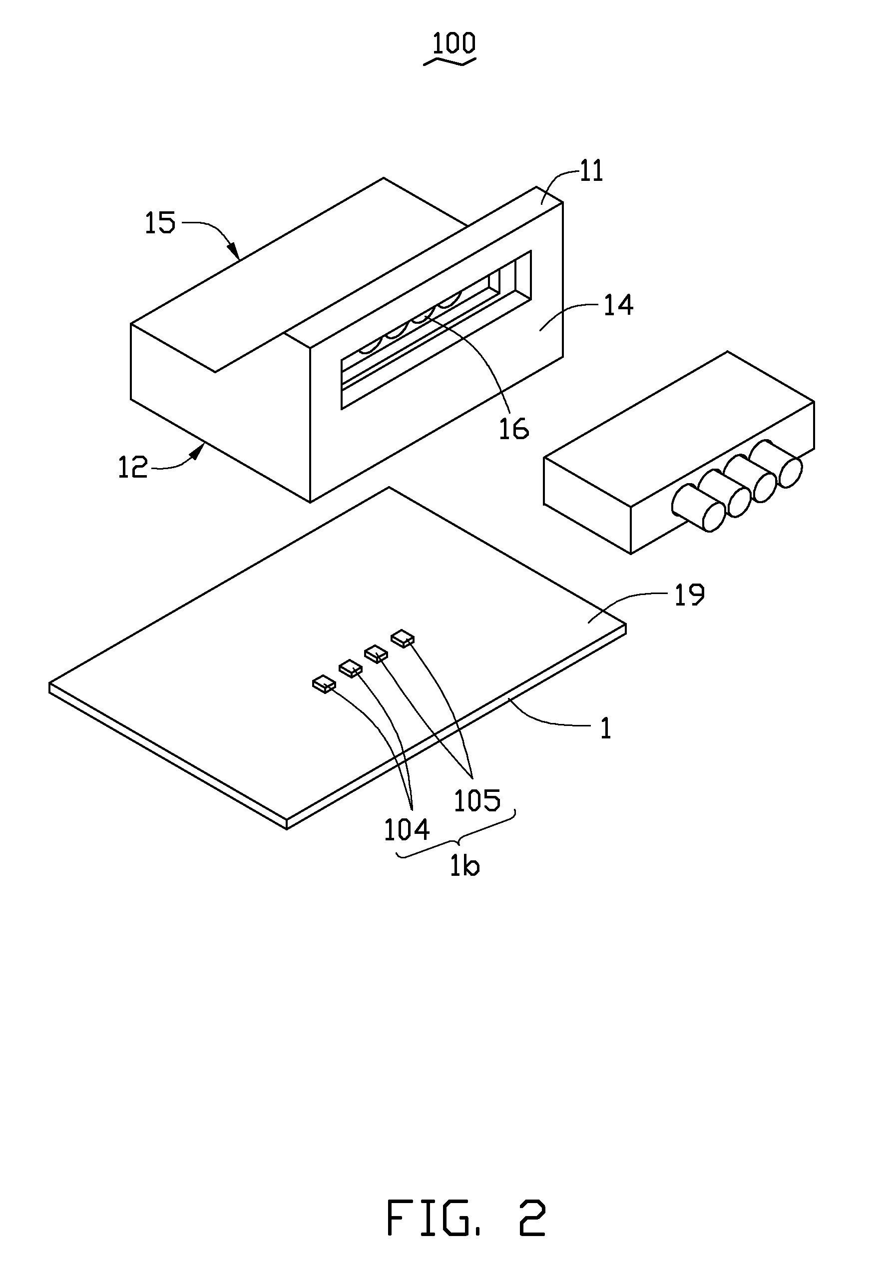
[0011]FIGS. 1-4 show an optical connector 100, according to an embodiment. The optical connector 100 includes a printed circuit board (PCB) 1, an optical-electric coupling element 10, a jumper 20 and four optical fibers 30. The optical-electric coupling element 10 is positioned on the PCB 1. The jumper 20 is detachably connected to the optical-electric coupling element 10. The four optical fibers 30 are received in the jumper 20.

[0012]The PCB 1 includes a supporting surface 1a. A photoelectric conversion module 1b is positioned on the supporting surface 1a and electrically connected to the PCB 1. The photoelectric conversion module 1b includes four photoelectric conversion chips, such as two laser diodes 104 and two photo diodes 105. The PCB 1 contains various circuits (not shown) that connect with the photo electric conversion module 1b, to drive the laser diodes 104 to emit light according to input for transmitting the input data, and for the demodulation of data in the light rece...


PUM


Abstract

An optical connector includes a printed circuit board (PCB), an optical-electric coupling element, and a jumper detachably attached to the optical-electric coupling element. The optical-electric coupling element is positioned on the PCB. The optical-electric coupling element includes at least two first coupling lenses and a sloped surface. The optical-electric coupling element defines a stepped receiving cavity in its sidewall. A bottom surface of the stepped receiving cavity forms at least two second coupling lenses. The jumper is detachably inserted into the stepped receiving cavity, and the jumper has at least two receiving holes receiving at least two optical fibers. Each optical fiber is optically aligned with a respective second coupling lens. Each second coupling lens is optically aligned with a respective first coupling lens via the sloped surface.

Description

BACKGROUND[0001]1. Technical Field[0002]The present disclosure relates to optical connectors, and particularly to an optical connector which has a sloped surface.[0003]2. Description of Related Art[0004]Optical connectors typically include a photoelectric conversion chip, such as a laser diode or a photo diode, and an optical fiber. The photoelectric conversion chip emits or receives light carrying data to or from the optical fiber for data transmission. In certain circumstances, the light path between the photoelectric conversion chip and the optical fiber must be bent about 90 degrees to reduce a length or height of the optical connector. This may be achieved by a reflective mirror tilted at 45 degrees with respect to the photoelectric conversion chip and the optical fiber. However, the essential step of accurately aligning the reflective mirror with the photoelectric conversion chip is a complex and difficult process.[0005]Therefore, it is desirable to provide an optical connecto...

Claims


Application Information

Patent Timeline
Patent Type & Authority Patents(United States)
IPC IPC(8): G02B6/43G02B6/42
CPCG02B6/42G02B6/4292G02B6/4214
Inventor HUNG, YI
Owner HON HAI PRECISION IND CO LTD
Why Eureka
Try Eureka