Organic vapor jet print head with solder joint

a technology of organic vapor jet and solder joint, which is applied in the direction of pliable tubular containers, manufacturing tools, solventing apparatus, etc., can solve the problem of limit the types of adhesives that can be used

Active Publication Date: 2015-02-03
RGT UNIV OF MICHIGAN
View PDF3 Cites 25 Cited by
  • Summary
  • Abstract
  • Description
  • Claims
  • Application Information

AI Technical Summary

Problems solved by technology

Due to the elevated temperatures at which some OVJP components must operate, there are some limitations on the types of adhesives than can be used, as polymer-based materials can soften, melt, or suffer from gradual degradation at such temperatures.

Method used


Image

  • Organic vapor jet print head with solder joint
  • Organic vapor jet print head with solder joint
  • Organic vapor jet print head with solder joint

Examples


Embodiment Construction

)

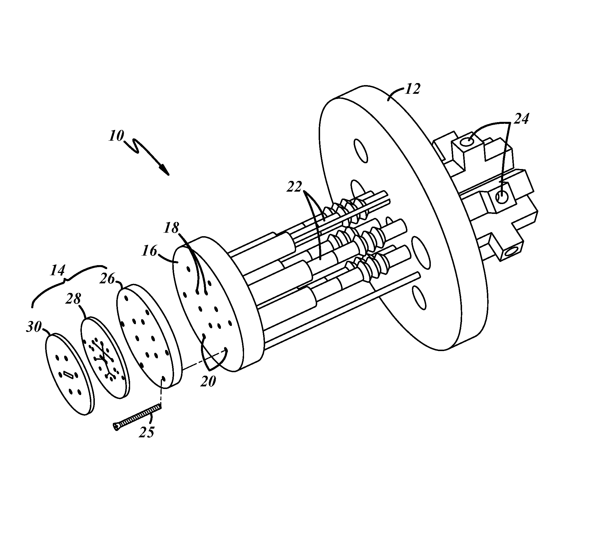
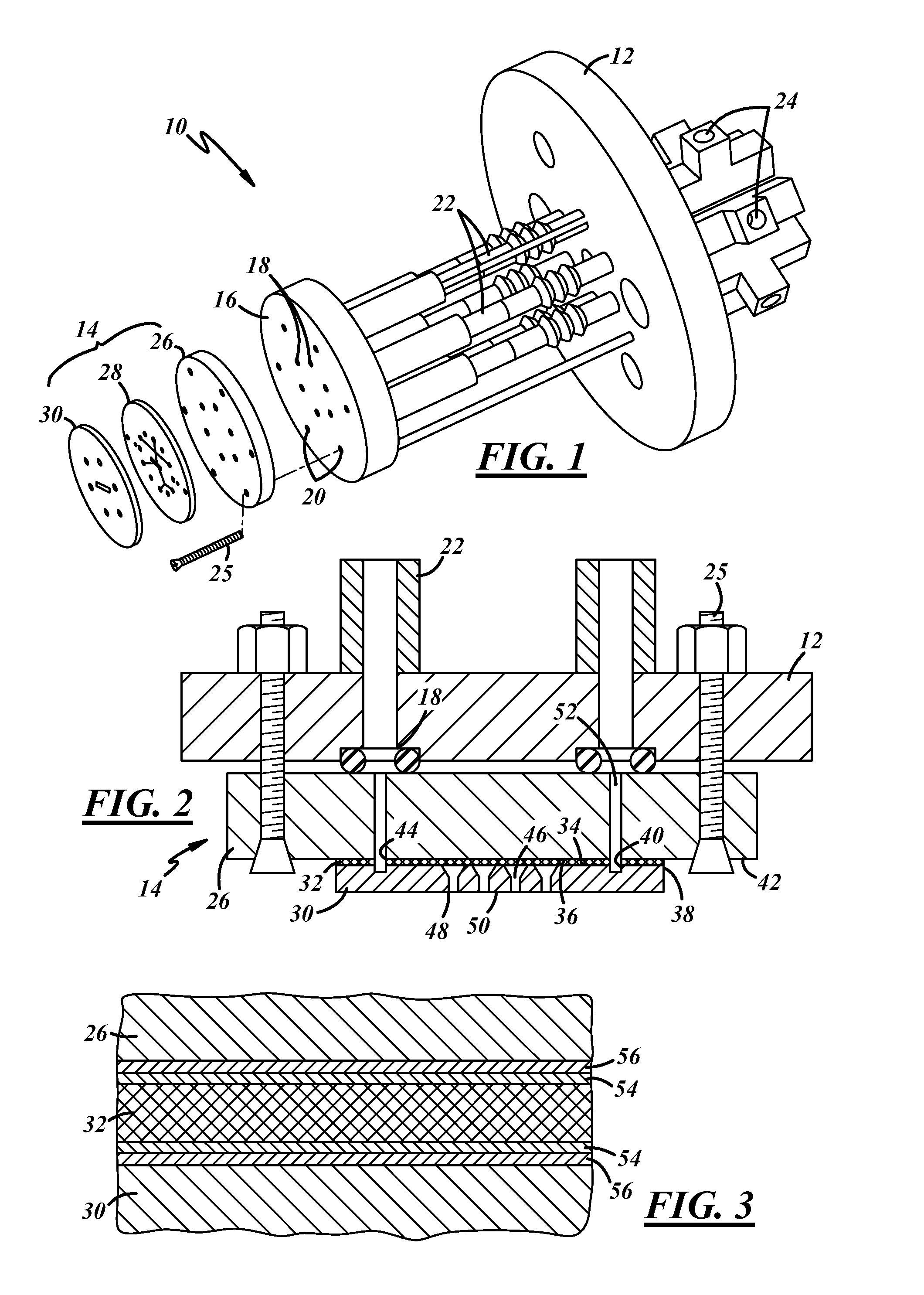
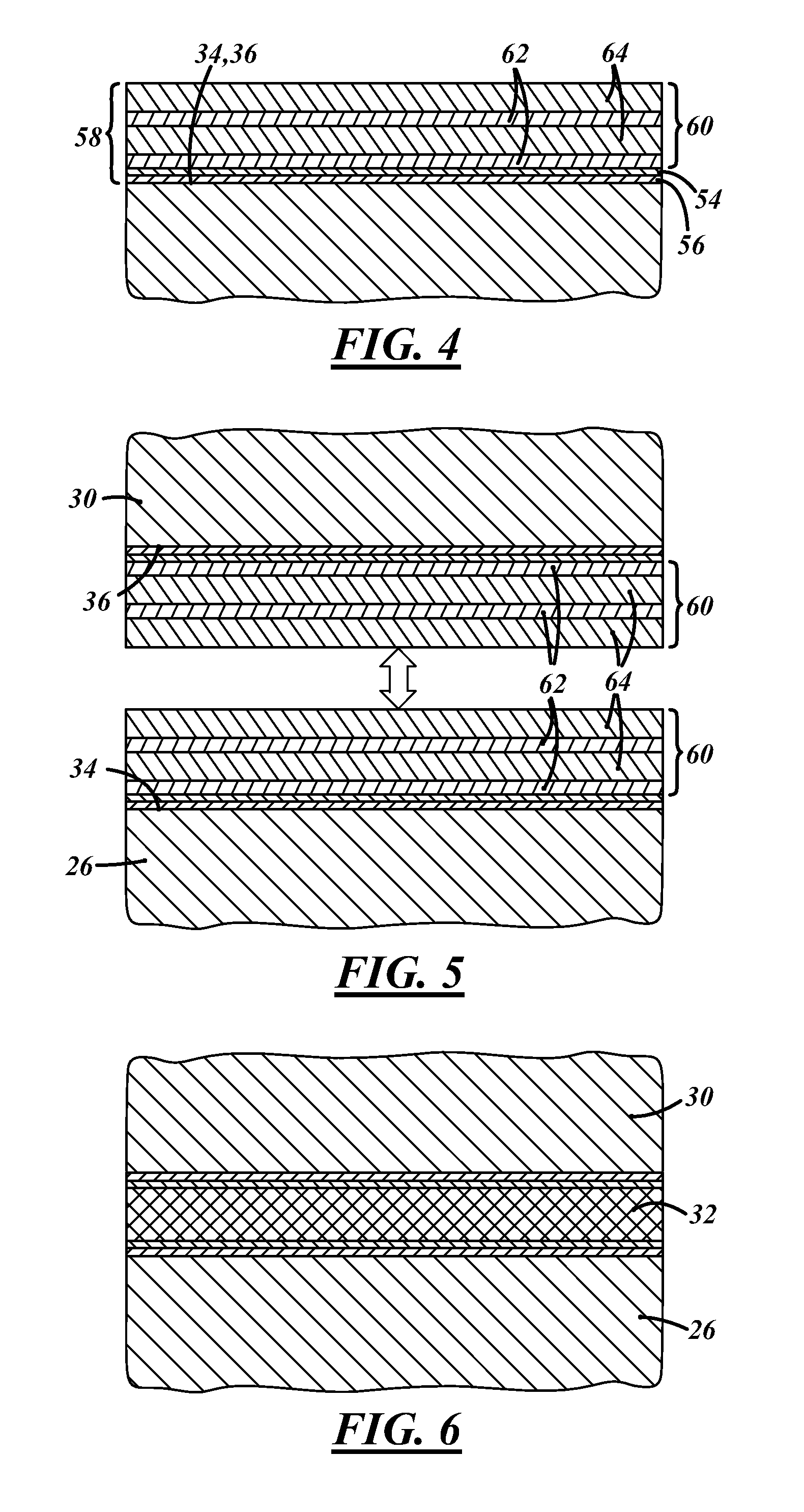
[0016]A solder joint may be used to attach components of an organic vapor jet printing device together with a fluid-tight seal that is capable of long-term performance at the elevated temperatures at which certain OVJP components operate. The solder joint may include one or more metals that are deposited over opposing component surfaces, such as a nozzle plate surface and / or a mounting plate surface. The solder joint may be formed from two or more metals that can be individually deposited and then combined to form an alloy. While presented here in the context of print head components for an OVJP device, various aspects of the solder joint described below may be used to join other OVJP components or other microfluidic delivery system components.

[0017]Referring to FIG. 1, a microfluidic delivery system is shown in the form of an OVJP printing device 10. The illustrated device 10 includes a fixture 12 and a microfluidic device 14 (shown in exploded view) adapted for attachment to the ...


PUM

PropertyMeasurementUnit
melting temperatureaaaaaaaaaa
thicknessaaaaaaaaaa
thicknessaaaaaaaaaa

Abstract

A solder joint may be used to attach components of an organic vapor jet printing device together with a fluid-tight seal that is capable of performance at high temperatures. The solder joint includes one or more metals that are deposited over opposing component surfaces, such as an inlet side of a nozzle plate and / or an outlet side of a mounting plate. The components are pressed together to form the solder joint. Two or more of the deposited metals may be capable of together forming a eutectic alloy, and the solder joint may be formed by heating the deposited metals to a temperature above the melting point of the eutectic alloy. A diffusion barrier layer and an adhesion layer may be included between the solder joint and each of the components.

Description

[0001]This application claims the benefit of U.S. Provisional Application No. 61 / 718,399, filed Oct. 25, 2012, the entire contents of which are hereby incorporated by reference.JOINT RESEARCH AGREEMENT[0002]The claimed invention was made by, on behalf of, and / or in connection with one or more of the following parties to a joint university corporation research agreement: Regents of the University of Michigan, Princeton University, The University of Southern California, and the Universal Display Corporation. The agreement was in effect on and before the date the claimed invention was made, and the claimed invention was made as a result of activities undertaken within the scope of the agreement.TECHNICAL FIELD[0003]This disclosure relates to structures and methods of making microfluidic devices such as those used in organic vapor jet printing systems.BACKGROUND OF THE INVENTION[0004]Various techniques have been developed for depositing and / or patterning organic materials on a substrate...

Claims


Application Information

Patent Timeline
Patent Type & Authority Patents(United States)
IPC IPC(8): B23K31/02B23K35/24B65D35/38B05C11/00
CPCB05C11/00C23C14/12C23C14/04C23C14/228B23K2101/00B05B1/00H10K71/135B23K1/0008B32B37/1284B32B37/18
Inventor FORREST, STEPHEN R.MCGRAW, GREGORY
Owner RGT UNIV OF MICHIGAN
Why Eureka
Try Eureka