Smart lock systems and methods

a smart lock and lock technology, applied in the field of electronic door locks, can solve the problem that the power transmitter cannot transmit electricity to the power receiver, and achieve the effect of improving the safety of the user and reducing the risk of th

Active Publication Date: 2015-02-03
SKYBELL TECH IP LLC
View PDF71 Cites 280 Cited by
  • Summary
  • Abstract
  • Description
  • Claims
  • Application Information

AI Technical Summary

Benefits of technology

[0023]The strike plate can be configured to be coupled to the door frame. The power transmitter can be configured to receive the electricity from the transformer. The power receiver can be electrically coupled to the electrical control system such that the power receiver is configured to provide the electricity to the electrical control system such that the electrical control system is capable of operating the bolt. The electrical control system can govern the position of a solenoid that is mechanically coupled to the bolt such that the solenoid can move the bolt to locked and unlocked positions.

Problems solved by technology

If the power transmitter is not placed within sufficient proximity relative to the power receiver, then the power transmitter is not capable of transmitting the electricity to the power receiver.

Method used


Image

  • Smart lock systems and methods
  • Smart lock systems and methods
  • Smart lock systems and methods

Examples


lock embodiments

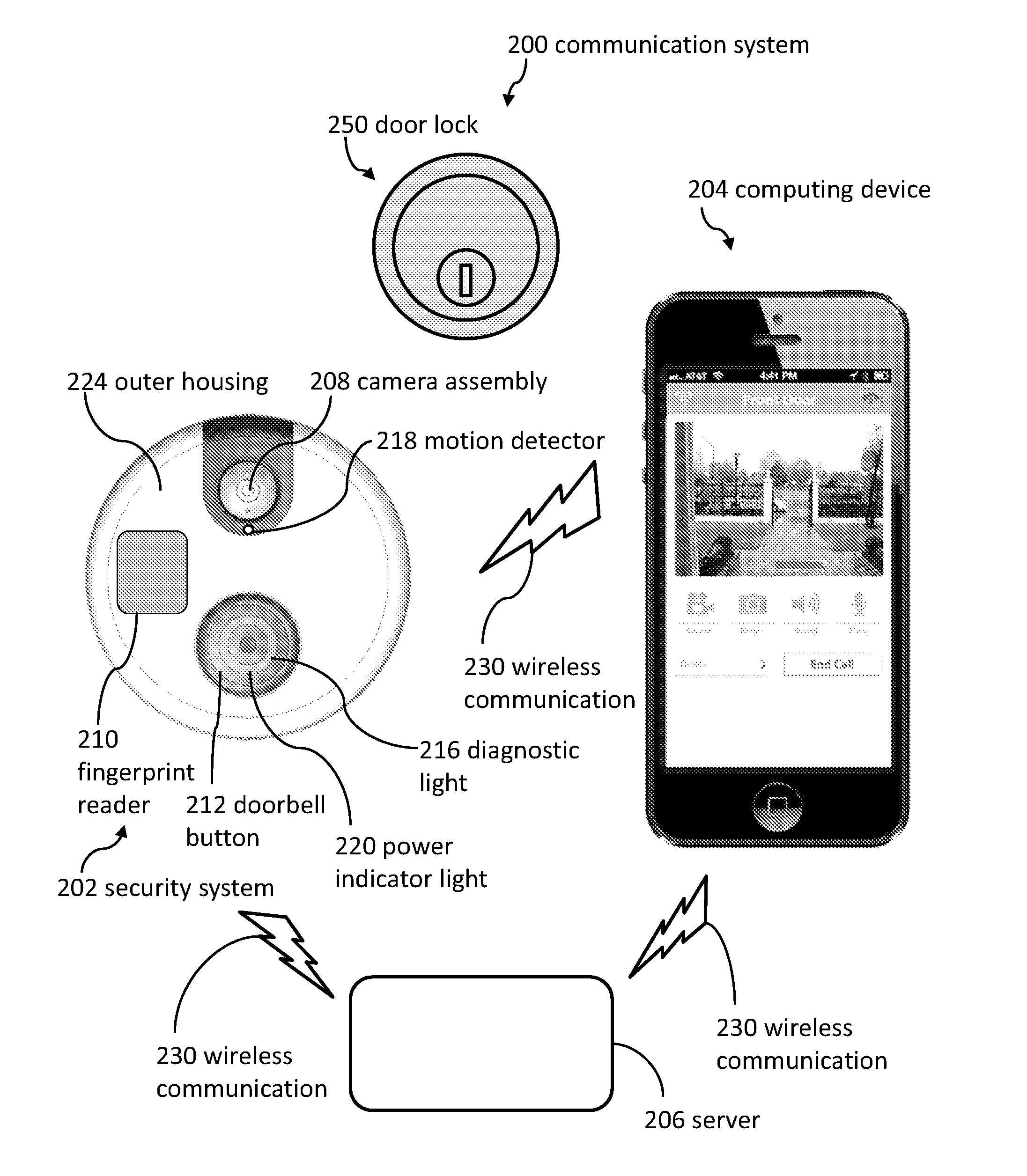
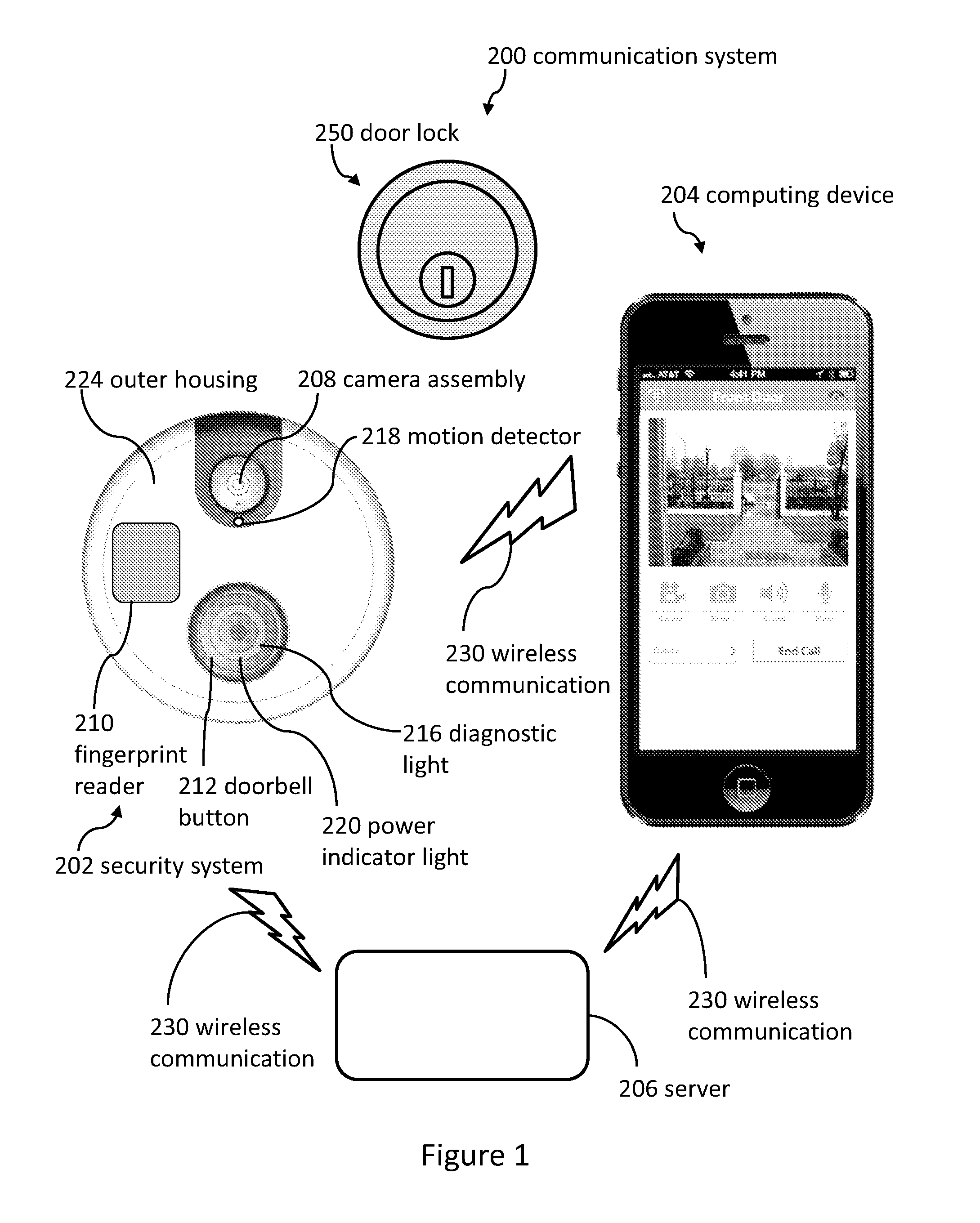
[0105]Referring now to FIGS. 3 and 4, in some embodiments, a doorbell (e.g., a security system 202) is attached to a wall 750 of a building 300 (e.g., the doorbell is not attached to a door). The lock 250 can be attached to the door 254. The doorbell can be configured to receive electricity from the building 300 through electrical wires 304. Then, the doorbell can provide electricity to the door lock 250 via various connection systems and methods.

[0106]FIG. 4 illustrates a diagrammatic view of a security system 202 providing electricity to a door lock 250. The door lock 250 can include batteries 752. The electricity from the security system 202 (e.g., a doorbell) can charge the batteries 752 of the door lock 250.

[0107]The building 300 can be electrically coupled to a power source 754. In some embodiments, the power source 754 provides 110 volts, 120 volts, or 220 volts (plus or minus 20 volts). The power source can be electrically coupled to a transformer 756 to convert the electric...

lock history embodiments

[0170]FIG. 9 illustrates a history 570 of lock-related events displayed on a user interface (e.g., of a smartphone, tablet, laptop, desktop computer, or television). The history can include when a door was locked and unlocked. The history can also include when the lock was set up and / or “paired” with the computing device 204 (show in FIG. 1).

[0171]Several embodiments comprise taking at least one image of the visitor on each occasion the visitor unlocks the lock 250; associating a time and a date with each additional image; and recording the additional images, the times, and the dates in the remote database 436. Methods can further comprise enabling the remote computing device 204 to display the images, the times, and the dates. For example, a user of the remote computing device 204 can search through the images to see the visitor who entered the building at a particular entry time (as captured in the history).

Watch Embodiments

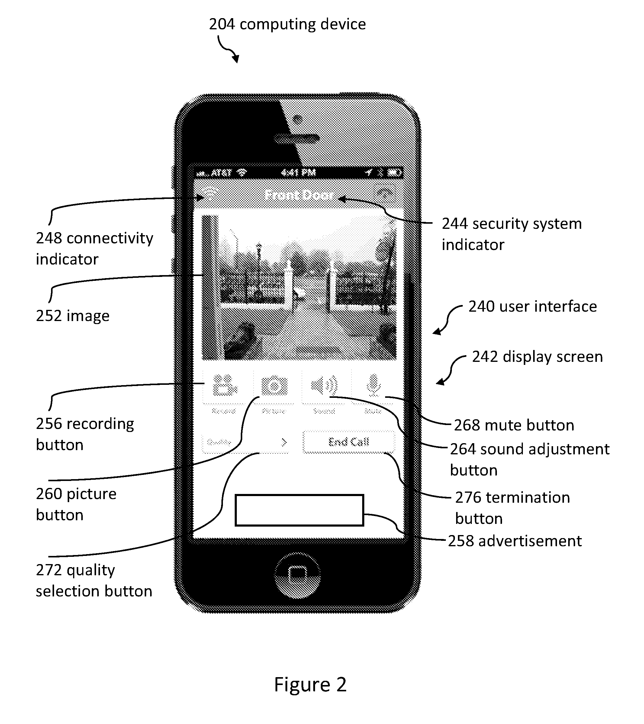
[0172]FIG. 10 illustrates a front view of a computing dev...


PUM


Abstract

A lock can receive electricity from a transformer of a doorbell chime while the lock is mounted on a door. The lock can be electrically coupled to the face plate. The face plate can be electrically coupled to the strike plate of the door frame. The strike plate of the doorframe can be electrically coupled to the transformer of the doorbell chime.

Description

CROSS-REFERENCE TO RELATED APPLICATIONS[0001]This application claims the benefit of U.S. Provisional Patent Application No. 62 / 018,606; filed Jun. 29, 2014; and entitled DOOR LOCK CHARGING SYSTEMS AND METHODS; the entire contents of which are incorporated herein by reference.[0002]This application claims the benefit of U.S. Provisional Patent Application No. 62 / 026,639; filed Jul. 19, 2014; and entitled WIRED HOME AUTOMATION METHODS AND SYSTEMS; the entire contents of which are incorporated herein by reference.[0003]This application claims the benefit of U.S. Provisional Patent Application No. 61 / 872,439; filed Aug. 30, 2013; and entitled DOORBELL COMMUNICATION SYSTEMS AND METHODS; the entire contents of which are incorporated herein by reference.[0004]This application claims the benefit of and is a continuation-in-part of U.S. Nonprovisional patent application Ser. No. 14 / 099,888; filed Dec. 6, 2013; and entitled DOORBELL COMMUNICATION SYSTEMS AND METHODS; the entire contents of wh...

Claims


Application Information

Patent Timeline
Patent Type & Authority Patents(United States)
IPC IPC(8): H04N9/47H04N7/18E05B47/00E05C1/12
CPCE05B47/0001E05C1/12E05B2047/0016E05B2047/0082H04M11/025H04N7/186H04N7/188E05B47/026E05B2047/0059E05B2047/0061E05B2047/0095G07C9/00174G07C9/00563G07C2009/00634G07C2009/00769G08B13/19684Y10T292/1021Y10T292/0969Y10T70/7062Y10T70/5199Y10T292/097Y10T292/1014
Inventor SCALISI, JOSEPH FRANK
Owner SKYBELL TECH IP LLC
Why Eureka
Try Eureka