Robot or haptic interface structure with parallel arms

a technology of haptic interface and parallel arms, which is applied in the direction of mechanical control devices, process and machine control, instruments, etc., can solve the problems of limited dynamic range, large working area, and limited working spa

Inactive Publication Date: 2015-02-10
COMMISSARIAT A LENERGIE ATOMIQUE ET AUX ENERGIES ALTERNATIVES
View PDF15 Cites 13 Cited by
  • Summary
  • Abstract
  • Description
  • Claims
  • Application Information

AI Technical Summary

Benefits of technology

[0017]In other words, the rotation of the handle is selectively geared down from the connecting segment, so that risks of collisions between the branches can be reduced and the working space can be increased.
[0019]In one advantageous embodiment, couplings between rotation and translation movements are reduced or even eliminated.

Problems solved by technology

This architecture gives a large working area, however it offers limited dynamics because each articulated body carries downstream bodies,the parallel architecture composed of several articulated branches arranged between a fixed base and a mobile platform itself supporting the handle manipulated by the user.
This architecture gives good dynamics but its working space is limited.
However, in parallel or mixed structures according to the state of the art, rotation movements are not sufficiently decoupled from translation movements, i.e. pure or almost pure rotation movements are not obtained.
Furthermore, the working space is limited due to risks of collision between branches.
These disadvantages also exist in robot structures according to the state of the art.

Method used


Image

  • Robot or haptic interface structure with parallel arms
  • Robot or haptic interface structure with parallel arms
  • Robot or haptic interface structure with parallel arms

Examples


first embodiment

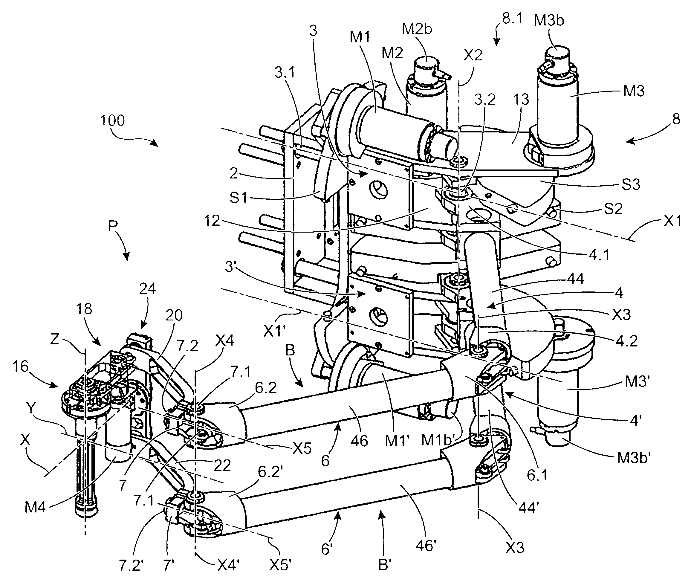
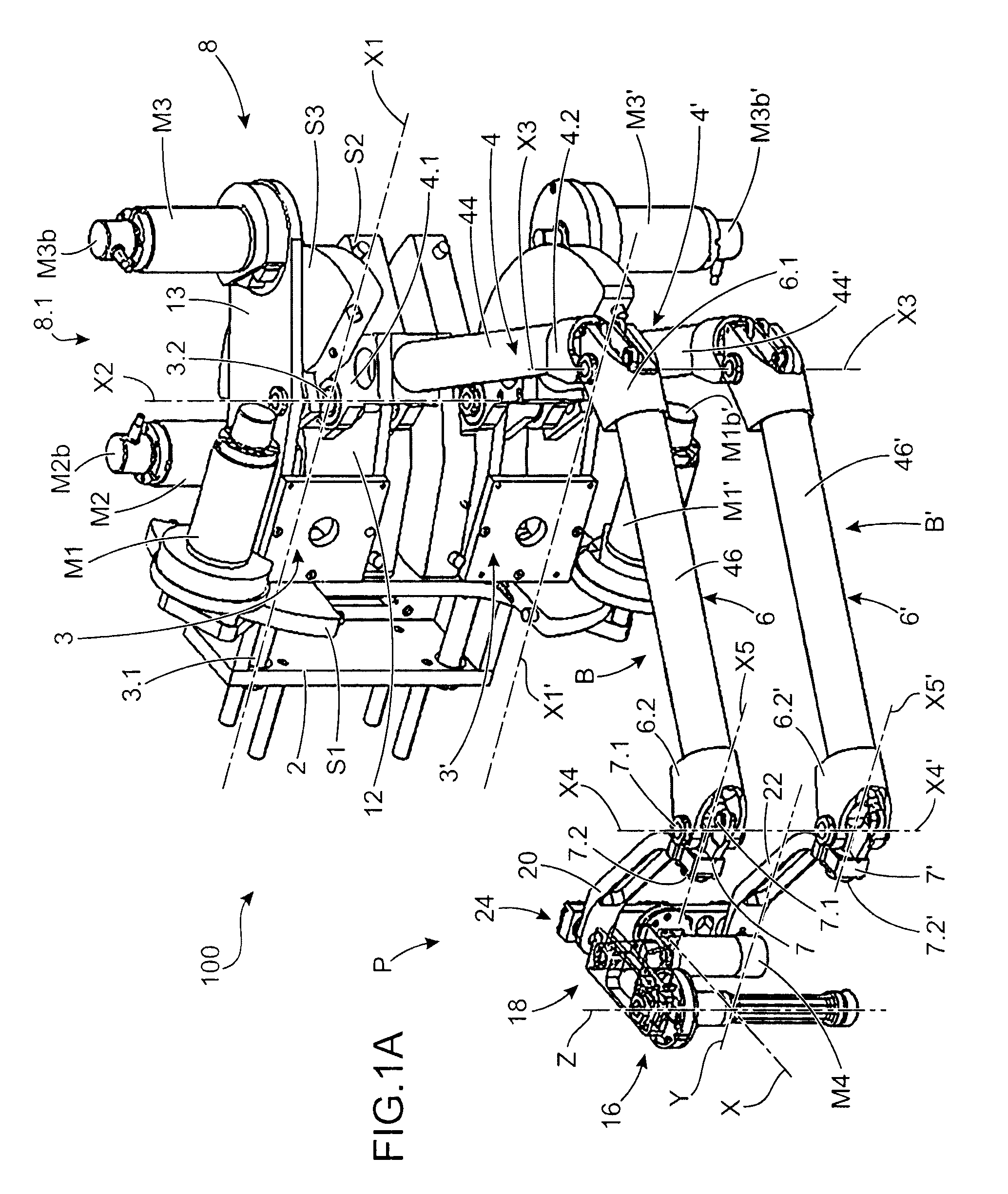
[0025] the structure comprises holding segments at the end of the forearms and the wrist joint also comprises two segments articulated in rotation on the holding segments, about the two rotation axes, the connecting segment being articulated in rotation on the first and the second segments, about the two axes parallel to the first axis, said segments having a curved shape and this curved part being approximately centred on the second axis, the structure also comprising means of holding the orientation of each rotation axis of the segments on the holding segments, such that the angles between given axes and each of said rotation axes of segments on the holding segments remain constant.

[0026]The rotation axes of the segments on the holding segments are advantageously each held parallel to said given axes.

[0027]Even more advantageously, the given axes are parallel to each other and the rotation axes of the segments on the holding segments are parallel to each other.

[0028]Said means of ...

second embodiment

[0037] the connecting segment is divided into two parts articulated to each other through a pivot connection, each part being articulated on a segment.

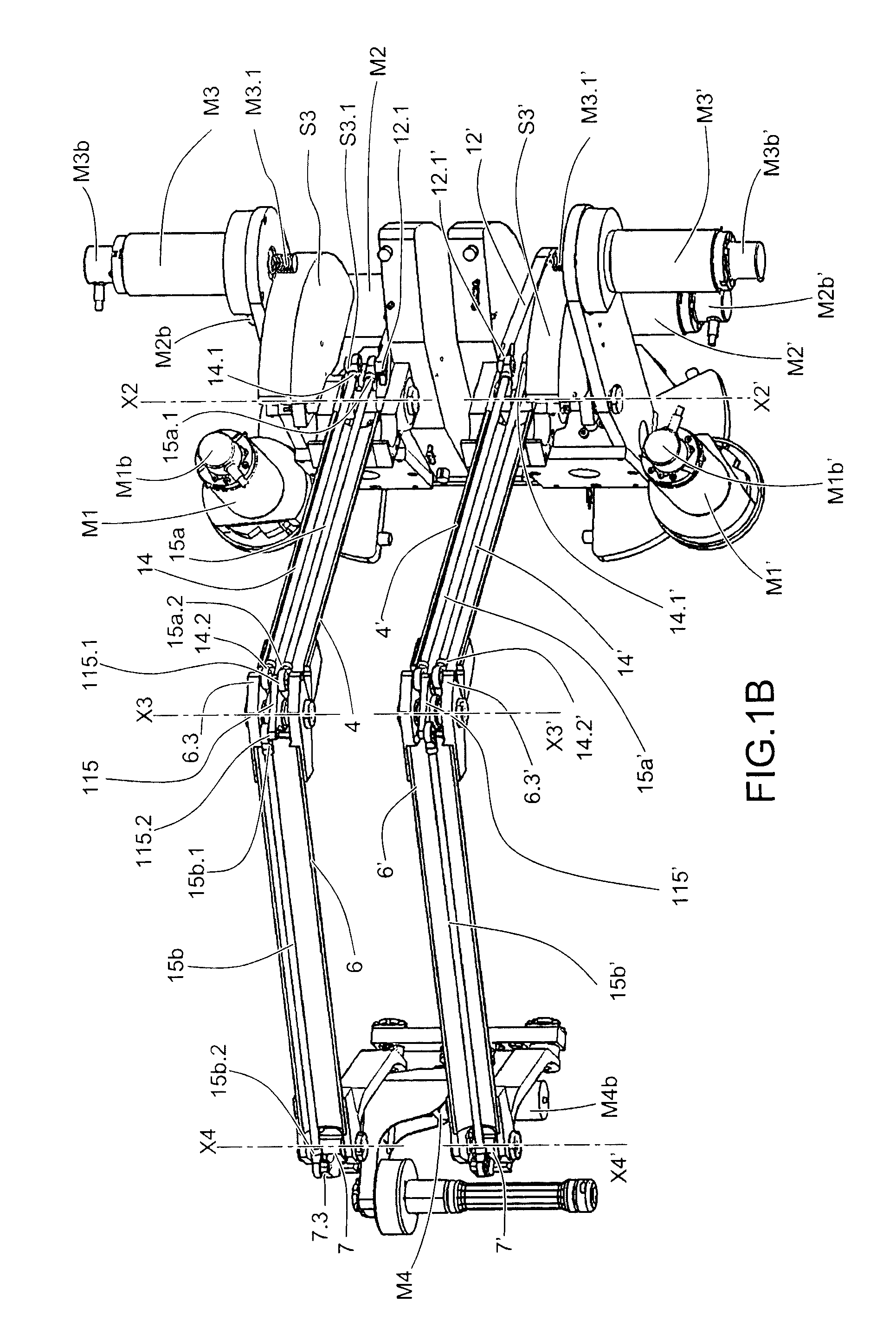
[0038]According to a first example of the second embodiment, the pivot connection is perpendicular to the rotation axes of the connecting segment on the segments, and is located between said axes.

[0039]According to a second example of the second embodiment, the connecting segment comprises a first approximately L-shaped element, one branch of which is articulated to one of the segments, about one of the rotation axes of the connecting segment on the segments, concurrent with one of the rotation axes of the segments on the forearms and the other branch is approximately parallel to the handle holder, and a second elbow-shaped element, said second element being articulated in rotation on the first element at a first end, said second element being articulated in rotation on the other segment, about an axis concurrent with the other rotati...


PUM


Abstract

A structure with six degrees of freedom for a robot or haptic interface including a base, two branches in parallel, and a wrist joint. The branches are installed articulated between the base and the wrist joint, the branches including a shoulder, an arm, and a forearm supporting the wrist joint. The wrist joint includes a connecting segment onto which a handle holder is articulated about a first rotation axis. A handle is articulated in rotation on the handle holder about a second rotation axis, the handle capable of being moved in rotation about the first axis, the second axis, and a third axis, and a mechanism gears down the rotation of the handle holder about at least the first rotation axis relative to rotation of the connecting segment.

Description

TECHNICAL FIELD AND PRIOR ART[0001]This invention relates to a robot or haptic interface structure with parallel arms, and to a robot and a haptic interface with six degrees of freedom comprising at least such a structure.[0002]A haptic interface enables an individual to interact with a virtual environment or to remotely control a robot, by applying a reaction to the user.[0003]This interface is usually manipulated by hand.[0004]In order to make the haptic interface as generic as possible, an attempt is made to have six degrees of freedom, with three degrees of freedom in translation and three degrees of freedom in rotation, so as to be able to manipulate the virtual environment or the remote robot in all directions.[0005]An attempt is also made to reduce configurations in which singularities can occur, i.e. configurations in which there are local disappearances of degrees of freedom or the appearance of uncontrolled movements.[0006]Finally, it is desirable to have the most uniform ...

Claims


Application Information

Patent Timeline
Patent Type & Authority Patents(United States)
IPC IPC(8): B25J17/00B25J17/02B25J18/00B25J3/04B25J13/02
CPCB25J13/02B25J3/04Y10S901/25B25J13/025Y10T74/20384Y10T74/20329Y10T74/20335
Inventor GOSSELIN, FLORIANFERLAY, FABIEN
Owner COMMISSARIAT A LENERGIE ATOMIQUE ET AUX ENERGIES ALTERNATIVES
Why Eureka
Try Eureka