Retractable power tap with low voltage cordless capability

a power tap and low-voltage technology, applied in the direction of connection contact material, application, coupling device connection, etc., can solve the problems of entanglement of electrical cords and communications wires connected to devices, the position of electrical power outlets and communication ports, and the cost of electrical materials rapidly increasing

Active Publication Date: 2015-02-10
BYRNE NORMAN R
View PDF18 Cites 49 Cited by
  • Summary
  • Abstract
  • Description
  • Claims
  • Application Information

AI Technical Summary

Problems solved by technology

Historically, one problem common to the use of electrical power and communications equipment is the positioning of electrical power outlets and communication ports, such as conventional RS-232 voice / data interface connectors.
However, the cost of electrical materials rapidly increases as the number of power source receptacles and associated equipment is increased.
In addition, and perhaps more importantly, the conventional design of single- or double-unit receptacles (for both electrical power and communications) within walls or floor surfaces, which are often a substantial distance from the devices to be powered or with which to communicate, cause unsightly and sometimes dangerous arrays, and may result in entanglements of the electrical cords and communications wires connected to the devices.
Again, however, the raceways can result in unsightly and entangled arrays of electrical cords and communication lines.
In addition, such raceways are often located on floor surfaces and are not particularly convenient.
Accordingly, these receptacles and communication ports are typically in a fairly “open” location, and the device cords again may prove to be unsightly and space consuming.
If, alternatively, the receptacles and communication ports are somewhat hidden from view, they can be difficult to access.
That is, the use of springs or similar arrangements can sometimes result in additional repair and maintenance costs.
Further, the use of a relatively long extrusion and spring assemblies can also result in higher initial costs.

Method used


Image

  • Retractable power tap with low voltage cordless capability
  • Retractable power tap with low voltage cordless capability
  • Retractable power tap with low voltage cordless capability

Examples


Embodiment Construction

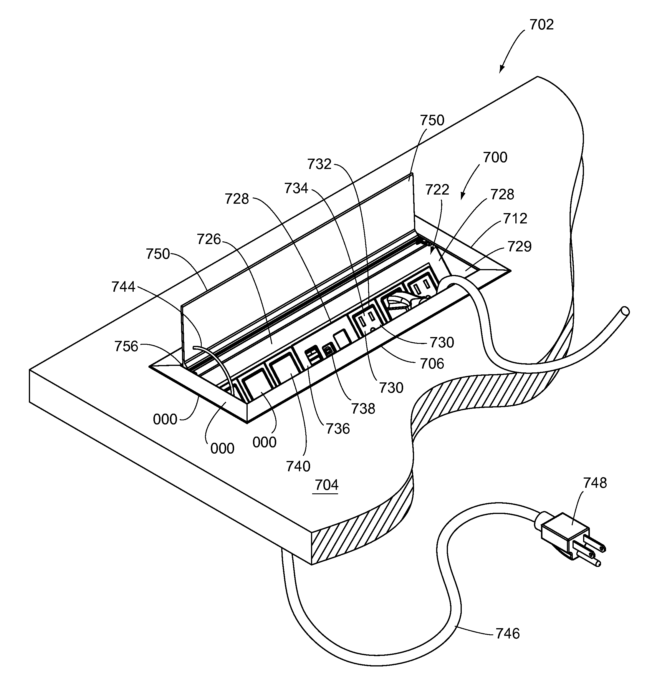
[0108]The principles of the invention are disclosed, by way of example, in a retractable power tap apparatus 700 with cordless charging capability as illustrated in FIGS. 52-67. The retractable power tap apparatus in accordance with the invention provides for multiple power distribution functions, such as providing high voltage AC power for energizing various electrical devices, as well as providing low voltage DC power for purposes of charging devices such as cell phones, PDA's and the like.

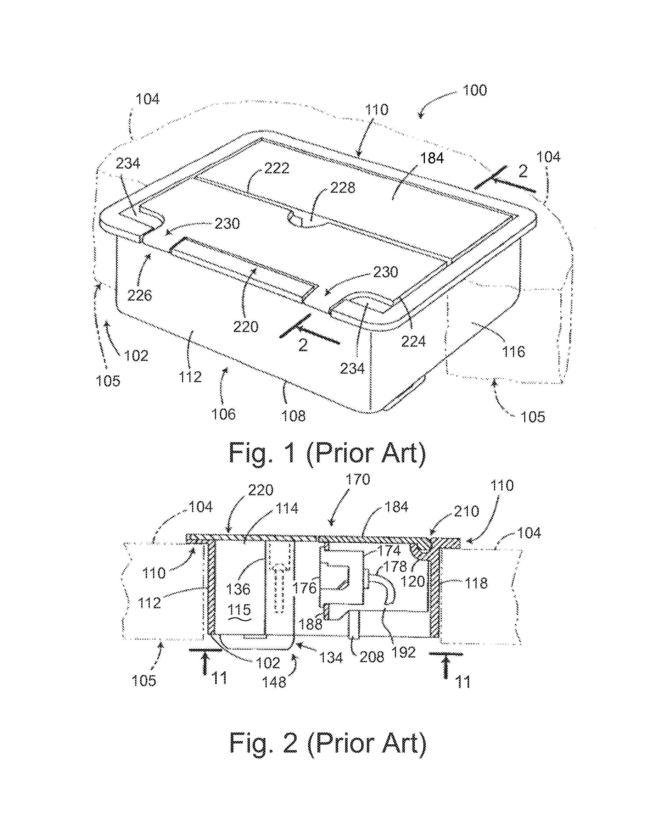
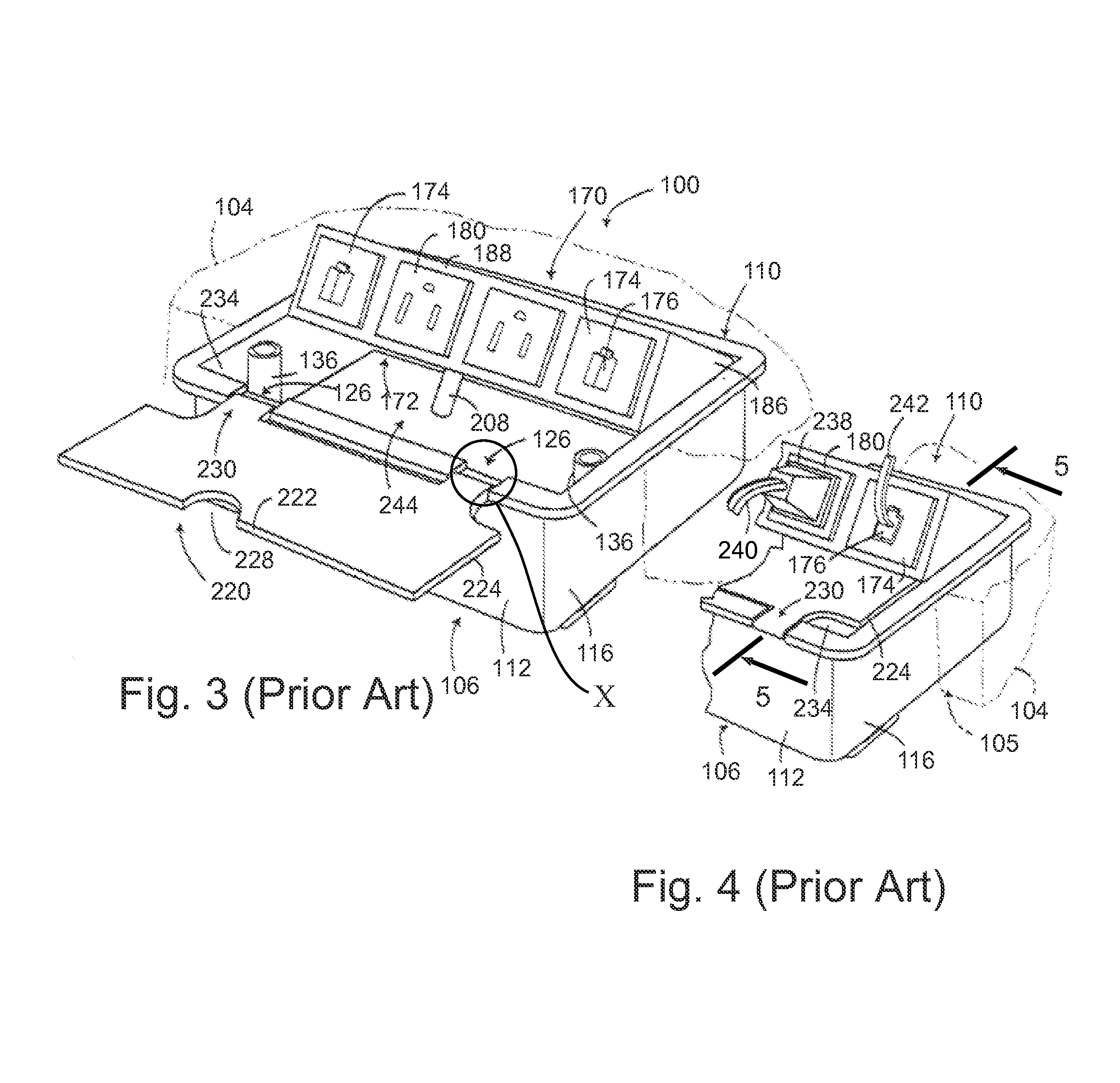
[0109]To more completely describe prior art associated with power and data centers, the following paragraphs describe an embodiment of a rotatable power and data center with storage area 100 as illustrated in FIGS. 1-17. This prior art power and data center 100 is disclosed in Byrne, U.S. Pat. No. 6,290,518 B1 issued Sep. 18, 2001. Following the description of the prior art power and data center 100 as illustrated in FIGS. 1-17, additional prior art power and data centers 300, 600 are described ...


PUM


Abstract

A power tap apparatus is positioned within a desk top or work surface. The apparatus includes a housing (708) and a high voltage power and / or data carriage. A cover is positioned above the stationary housing. A low voltage charging pad is mounted to the cover and includes a surface of insulating material with a series of conductive charging lanes mounted thereto.

Description

CROSS-REFERENCE TO RELATED APPLICATIONS[0001]This application is based upon and claims priority of U.S. patent application Ser. No. 13 / 159,070 filed Jun. 13, 2011 (abandoned), and of U.S. provisional application Ser. No. 61 / 354,055 filed Jun. 11, 2010.STATEMENT REGARDING FEDERALLY SPONSORED RESEARCH OR DEVELOPMENT[0002]Not applicable.REFERENCE TO A MICROFICHE APPENDIX[0003]Not applicable.FIELD OF THE INVENTION[0004]The invention relates to electrical power, and power and data distribution systems and, more particularly, to retractable power taps having capabilities of multiple electrical functions, including low voltage power-related functions.DESCRIPTION OF RELATED ART[0005]The use of computers, sophisticated telecommunications equipment and other electronic devices is continuing to rapidly increase in commercial, industrial and other office environments. As a result, the importance of efficiently supplying power throughout these environments is also increasing. Historically, one p...

Claims


Application Information

Patent Timeline
Patent Type & Authority Patents(United States)
IPC IPC(8): H01R4/60H01R13/447H01R35/04
CPCH01R13/447H01R35/04
Inventor BYRNE, NORMAN R.PATE, RANDELL ERNESTWARWICK, TIMOTHY JOHNSULTANA, VICTOR ALEXANDER
Owner BYRNE NORMAN R
Why Eureka
Try Eureka