Airbag device

a technology for airbags and occupants, applied in the direction of pedestrian/occupant safety arrangements, vehicular safety arrangments, vehicle components, etc., can solve the problems of corresponding decreases in the speed at which the airbag enters the vehicle cabin, and achieves the effect of reducing the speed of the airbag, facilitating the strength requirement and shape requirement set, and not reducing the deployment speed

Active Publication Date: 2015-02-17
ASHIMORI INDS
View PDF30 Cites 7 Cited by
  • Summary
  • Abstract
  • Description
  • Claims
  • Application Information

AI Technical Summary

Benefits of technology

[0016]According to the present invention, when the airbag is deployed, it is possible to cause the accordion-folded portion to directly push the roll-folded portion in a compact state, in which it is folded into two, from the storage portion toward the vehicle-cabin-interior side, in the vehicle width direction. That is, the airbag is not strongly pushed downward at the initial stage of deployment. Thus, because the airbag is not strongly urged against the lower portion of the airbag storage portion (e.g., an upper end portion of the pillar trim) at the initial stage of deployment, as in the conventional configuration, the deployment speed does not decrease, and quick deployment is possible. Furthermore, in the attachment of the pillar trim, it is possible to ease the strength requirement and shape requirement set based on an assumption that it comes into contact with the airbag and diverts the deployment direction of the airbag.

Problems solved by technology

However, as has been described above, because this airbag device is configured such that the supply path portion 115, which is inflated at the initial stage of deployment, strongly pushes the roll-folded portion 138 downward at the beginning of inflation and deployment, causing it to strike the inclined upper end 107a of the pillar garnish 107, that is, such that the roll-folded portion 138 is caused to strike the inclined upper end 107a of the pillar garnish 107 before entering the vehicle-interior side I, there is a problem in that the speed at which it enters the vehicle cabin decreases correspondingly.

Method used


Image

  • Airbag device
  • Airbag device
  • Airbag device

Examples


Embodiment Construction

[0024]An embodiment of an airbag device according to the present invention will be described with reference to the drawings.

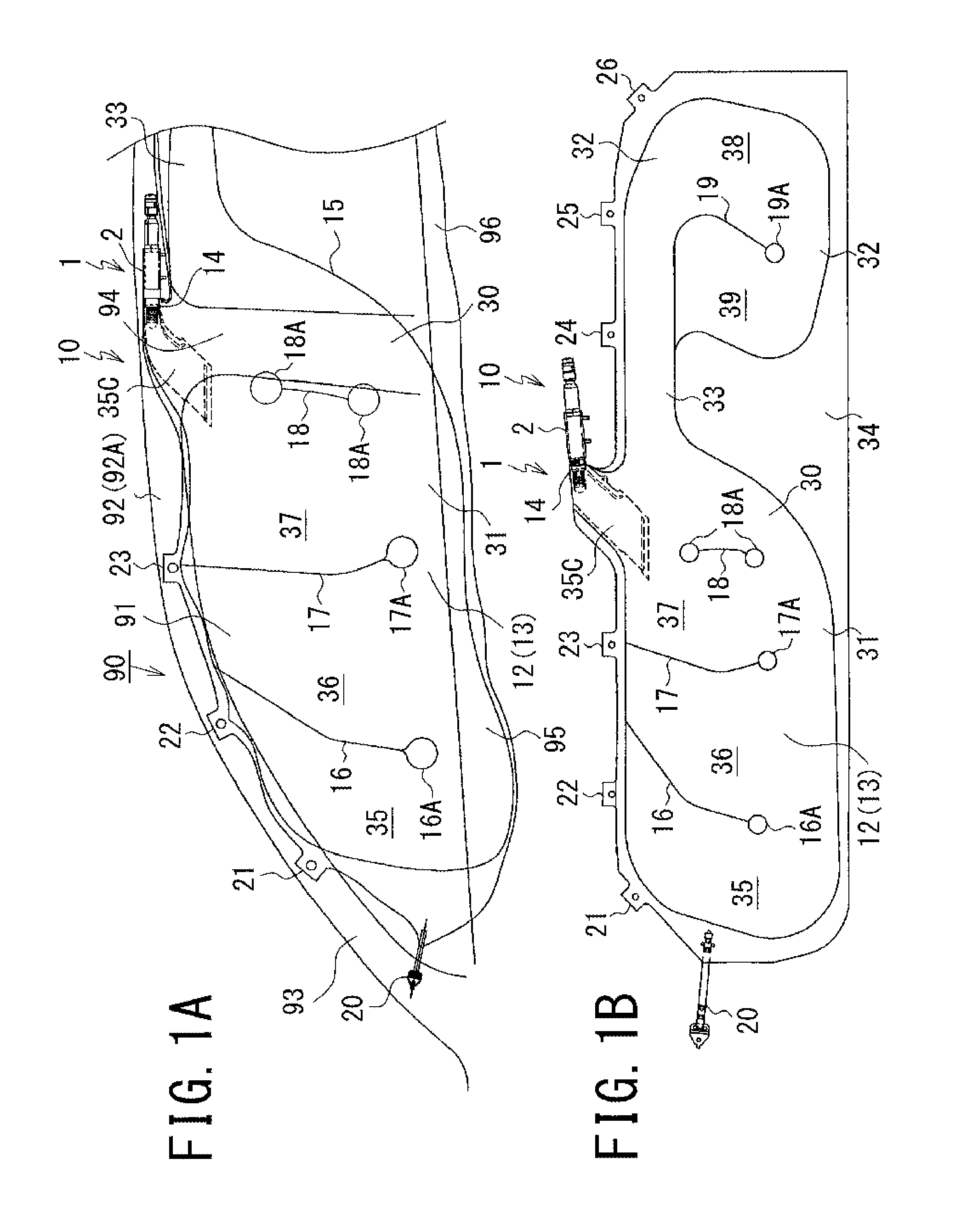
[0025]An airbag device according to this embodiment is of a type that inflates and deploys an airbag downward from the upper part (upper edge) of a side wall inside a vehicle cabin, along the side wall inside the vehicle cabin, and includes an inflatable airbag folded in a predetermined state, and an inflator that generates gas and supplies the gas to the airbag in an emergency of the vehicle or when an impact is detected.

[0026]The following description will be given by taking, as an example, a side airbag device that inflates and deploys an airbag like a curtain from the upper part of the side wall inside the vehicle cabin and deploys the airbag over a predetermined area, on the vehicle-interior side, of the side wall inside the vehicle cabin, from a driver's seat and a passenger's seat to rear seats on the rear side of the vehicle to protect, mainly, the head...


PUM


Abstract

An action of once strongly pressing an airbag against a pillar trim at the initial stage of deployment is omitted to enable the airbag to be quickly inflated and deployed without reducing the deployment speed thereof. An airbag device includes a folded airbag (10) that is attached to an upper part of a side wall inside a vehicle cabin in the front-rear direction of a vehicle, and an inflator that inflates and deploys the airbag (10) to the lower side of the vehicle. The airbag (10) includes a roll-folded portion (10R) rolled from one end thereof opposite from an attaching side, and an accordion-folded portion (10J) continuous with the roll-folded portion (10R) and folded in an accordion manner. The accordion-folded portion (10J) is folded so as to be located at a side of the roll-folded portion (10R). The accordion-folded portion (10J) is formed by folding the roll-folded portion (10R) into two and making accordion folds from the two-folded portion so as to have the same width as the width (L2) of the two-folded roll-folded portion (10R).

Description

CROSS REFERENCE TO RELATED APPLICATIONS[0001]This is a National Stage of International Application No. PCT / JP2012 / 065502 filed Jun. 18, 2012, claiming priority based on Japanese Patent Application No. 2011-139791 filed Jun. 23, 2011, the contents of all of which are incorporated herein by reference in their entirety.TECHNICAL FIELD[0002]The present invention relates to an airbag device that is installed in a vehicle, such as a car, to protect an occupant, and, for example, it relates to an airbag device that deploys, in a vehicle cabin, an airbag like a curtain in the front-rear direction of the vehicle.BACKGROUND ART[0003]A known airbag device in the related art is configured to store a folded airbag in the upper part of a side wall inside a vehicle cabin, a vehicle-interior side portion thereof being covered with an airbag cover, and is configured to quickly inflate and deploy an airbag along the side wall inside the vehicle cabin, while reducing the amount by which the airbag pro...

Claims


Application Information

Patent Timeline
Patent Type & Authority Patents(United States)
IPC IPC(8): B60R21/237B60R21/213B60R21/231B60R21/232B60R21/2346
CPCB60R21/237B60R21/213B60R21/232B60R21/23138B60R21/2346
Inventor MAITA, AKIHIROKONISHI, SHUHEIHASHIZUME, TOMOKI
Owner ASHIMORI INDS
Why Eureka
Try Eureka