Multilayer common mode filter

a filter and common mode technology, applied in the field of multilayer common mode filters, to achieve the effect of enhancing magnetic coupling, convenient arrangement, and enhancing magnetic coupling

Active Publication Date: 2015-02-17
TDK CORPARATION
View PDF7 Cites 1 Cited by
  • Summary
  • Abstract
  • Description
  • Claims
  • Application Information

AI Technical Summary

Benefits of technology

[0006]An object of the present invention is to provide a multilayer common mode filter capable of enhancing the magnetic coupling between the first coil and the second coil.
[0008]In the multilayer common mode filter according to the present invention, the portion located inside the first coil and the second coil in the nonmagnetic section includes the first regional portion and the second regional portion adjacent to each other when viewed from the laminated direction. When viewed from the laminated direction, the first through-hole conductor and the second through-hole conductor are located in the first regional portion so as to be adjacent to each other. The magnetic core section is located in the second regional portion. As a consequence of these, the distance between the first through-hole conductor and the second through-hole conductor is short and thus the first through-hole conductor and the second through-hole conductor are easy to be magnetically coupled. Therefore, the present invention successfully enhances the magnetic coupling between the first coil and the second coil.
[0009]The multilayer common mode filter may be configured as follows: the element body has a substantially rectangular parallelepiped shape; the portion located inside the first coil and the second coil in the nonmagnetic section has a shape elongated in a longitudinal direction of the element body when viewed from the laminated direction; the first through-hole conductor and the second through-hole conductor are located so as to be lined up along the longitudinal direction, when viewed from the laminated direction. In this case, the first through-hole conductor and the second through-hole conductor can be readily arranged close together, while preventing a short circuit between each through-hole conductor and each coil conductor. As a consequence of this, it is feasible to further enhance the magnetic coupling between the first coil and the second coil.
[0011]The first coil and the second coil may be arranged in the nonmagnetic section further so that the second coil conductor and the third coil conductor are adjacent to each other in the laminated direction. In this case, the magnetic coupling is achieved not only between the first coil conductor and the third coil conductor and between the second coil conductor and the fourth coil conductor, but also between the second coil conductor and the third coil conductor. As a consequence of this, it is feasible to further enhance the magnetic coupling between the first coil and the second coil.

Problems solved by technology

However, the multilayer common mode filter described in the foregoing Laid-Open Publication No. 2012-124470 may have the problem as described below.

Method used


Image

  • Multilayer common mode filter
  • Multilayer common mode filter
  • Multilayer common mode filter

Examples


Embodiment Construction

[0021]The preferred embodiments of the present invention will be described below in detail with reference to the accompanying drawings. In the description the same elements or elements with the same functionality will be denoted by the same reference signs, without redundant description.

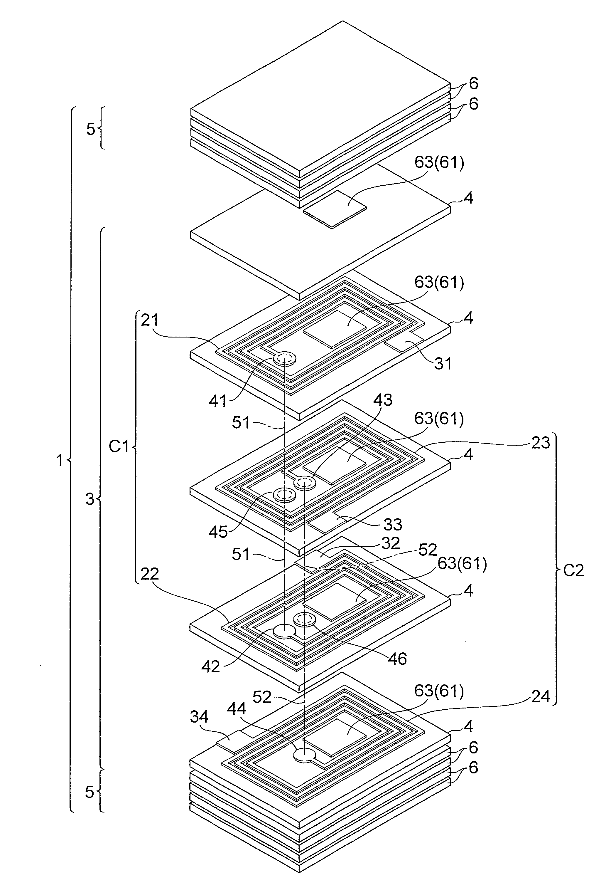
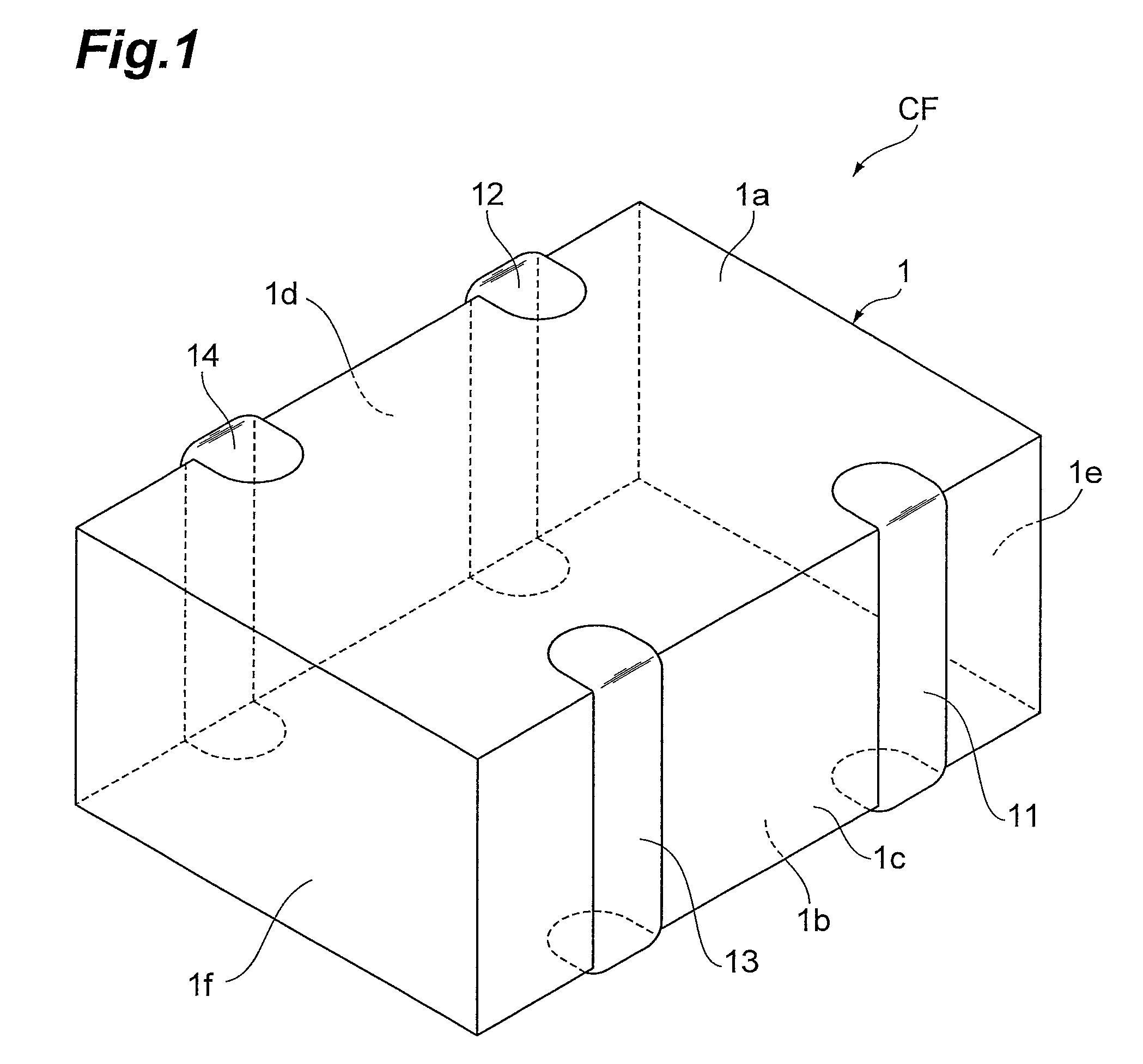
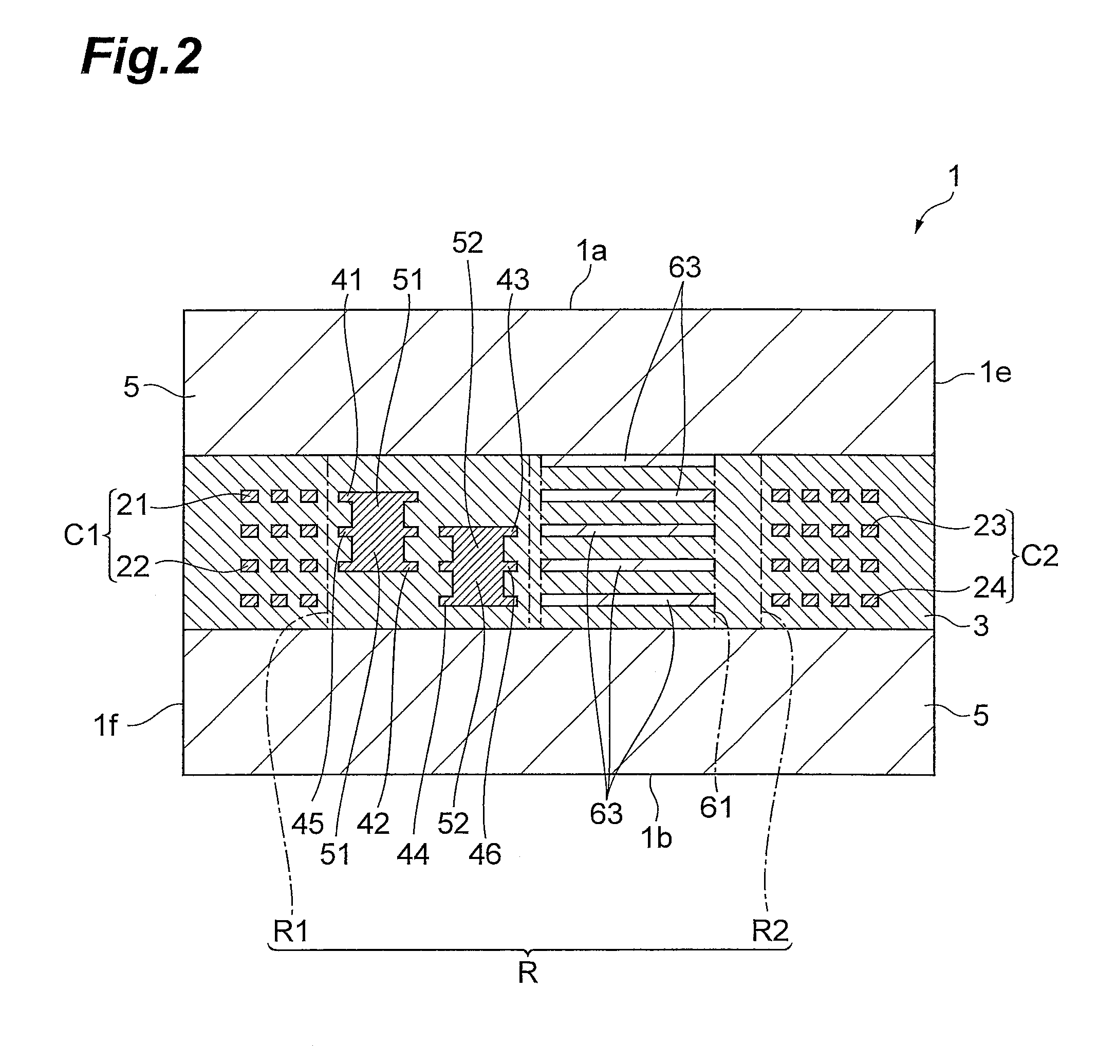
[0022]A configuration of a multilayer common mode filter CF according to an embodiment of the present invention will be described with reference to FIGS. 1 to 3. FIG. 1 is a perspective view showing the multilayer common mode filter according to the present embodiment. FIG. 2 is a drawing for explaining a cross-sectional configuration of an element body. FIG. 3 is an exploded perspective view showing a configuration of the element body.

[0023]The multilayer common mode filter CF, as shown in FIGS. 1 to 3, is provided with an element body 1 and with first to fourth terminal electrodes 11 to 14 arranged on the exterior surface of the element body 1. The element body 1 has a nonmagnetic section 3, and a ...


PUM


Abstract

A first coil is configured in such a structure that first and second coil conductors are connected by a first through-hole conductor. A second coil is configured in such a structure that third and fourth coil conductors are connected by a second through-hole conductor. The first and second coils are arranged in a nonmagnetic section consisting of nonmagnetic layers. A portion located inside the first coil and the second coil in the nonmagnetic section includes a first regional portion and a second regional portion adjacent to each other when viewed from a laminated direction of the nonmagnetic layers. The first and second through-hole conductors are located in the first regional portion so as to be adjacent to each other, when viewed from the laminated direction. A magnetic core section comprised of a magnetic material is located in the second regional portion when viewed from the laminated direction.

Description

BACKGROUND OF THE INVENTION[0001]1. Field of the Invention[0002]The present invention relates to a multilayer common mode filter.[0003]2. Related Background Art[0004]There is a known multilayer common mode filter provided with an element body having a nonmagnetic section in which a plurality of nonmagnetic layers are laminated together, a first coil, a second coil, and a magnetic core section made of a magnetic material (e.g., cf. Japanese Patent Application Laid-Open Publication No. 2012-124470). Each of the first coil and the second coil is composed of a pair of coil conductors of a spiral shape connected by a through-hole conductor. The magnetic core section is arranged in the nonmagnetic section so as to be located inside the first and second coils when viewed from a laminated direction of the nonmagnetic layers.SUMMARY OF THE INVENTION[0005]However, the multilayer common mode filter described in the foregoing Laid-Open Publication No. 2012-124470 may have the problem as describ...

Claims


Application Information

Patent Timeline
Patent Type & Authority Patents(United States)
IPC IPC(8): H03H7/00H03H1/00H03H7/42
CPCH03H7/427H03H2001/0085
Inventor YOSHINO, MAKOTOHATTORI, TAKUO
Owner TDK CORPARATION
Why Eureka
Try Eureka