Coil device

a technology of coils and coils, applied in the manufacture of coils, basic electric elements, electrical apparatuses, etc., can solve the problems of secondary side weakening of magnetic couplings, achieve effective control or reduction of secondary side windings, enhance magnetic couplings on the side of the second winding portion, and reduce manufacturing errors of leakage inductan

Active Publication Date: 2020-03-05
WUXI TDK LAMBDA ELECTRONICS CO LTD
View PDF5 Cites 0 Cited by
  • Summary
  • Abstract
  • Description
  • Claims
  • Application Information

AI Technical Summary

Benefits of technology

[0009]The coil device according to the present invention has a structure in which the first winding portion and the second winding portion are respectively wound around both sides of the first partition portion, and the winding of the second winding portion is wound at a predetermined position on both sides of the second partition portion. With such a winding configuration, the second winding portion can be easily wound at a predetermined position, thereby effectively controlling or reducing the leakage inductance manufacturing error between the primary side and the secondary side due to the difference in the secondary side winding, and at the same time strengthening the magnetic coupling on one side of the second winding portion.
[0025]With the above manufacturing method, it is possible to obtain a coil device in which the magnetic coupling on the side of the second winding portion is enhanced and the leakage inductance manufacturing error between the primary side and the secondary side due to the difference in the secondary side winding is effectively controlled or reduced.

Problems solved by technology

However, in the coil device described above, when multiple coils are wound on the secondary side, it is difficult for the secondary winding to be wound at a predetermined position, resulting in weakening of the magnetic coupling on the secondary side.

Method used


Image

  • Coil device
  • Coil device
  • Coil device

Examples


Embodiment Construction

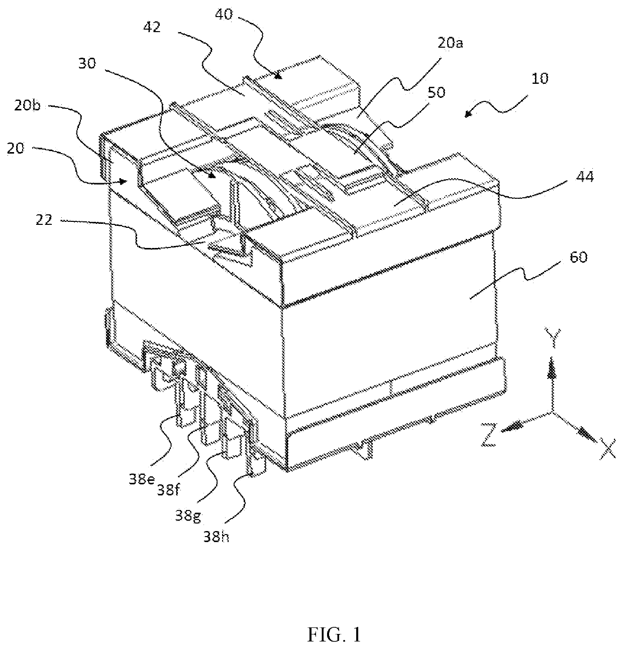
[0031]FIG. 1 is a perspective view of a coil device 10 according to a first embodiment of the present invention. The coil device 10 has a magnetic core 20, a bobbin 30, a support 40, a coil body 50, an insulating tape 60, and the like. The coil device 10 is a horizontal coil device in which the axial direction of the central shaft portion 22 of the magnetic core 20 is parallel to the mounting surface of the coil device 10, but the coil device according to the present invention is not limited to the horizontal type, and may be a vertical coil device in which the axial direction of the central shaft portion is parallel to the normal to the mounting surface.

[0032]In addition, in the description of the coil device 10 according to the embodiment, as shown in FIG. 1, the axial direction of the central shaft portion 22 of the magnetic core 20 is a Z-axis direction, and the normal direction of the mounting surface is a Y-axis direction, the direction perpendicular to the Z-axis direction an...


PUM

PropertyMeasurementUnit
insulation distanceaaaaaaaaaa
structureaaaaaaaaaa
L-shaped structureaaaaaaaaaa

Abstract

A coil device includes a bobbin including a hollow cylindrical portion and first and second flanges disposed at ends of the hollow cylindrical portion, and having a first partition located between the first and second flange and a second partition located between the first partition and second flange; the first winding wound around the outer periphery of the hollow cylindrical portion between first partition and the first flange; the second winding wound around the outer peripheral surface of the hollow cylindrical portion between the first partition and the second flange, and wound around both sides of the second partition according to a predetermined position. The coil device can wind the winding wire of the second winding at a predetermined position, thereby reinforcing the secondary side magnetic coupling while controlling or reducing the leakage inductance manufacturing error between the primary and secondary side due to difference in the secondary side winding.

Description

BACKGROUND(a) Field[0001]The present invention relates to a coil device and the like, and more particularly, to a coil device and the like in which a plurality of winding portions are wound and applied to a switching power supply.(b) Description of the Related Art[0002]Patent Document 1 proposes a coil device in which a partition portion is provided on the outer peripheral surface of the bobbin, the primary side winding is formed on one side of the partition portion, and the secondary side winding is formed on the other side (see Patent Document 1). Such a coil device has a configuration that is advantageous for thinning.[0003]Patent Document 1: Japanese Utility Model Application Publication No. H5-48313.[0004]However, in the coil device described above, when multiple coils are wound on the secondary side, it is difficult for the secondary winding to be wound at a predetermined position, resulting in weakening of the magnetic coupling on the secondary side.SUMMARY[0005]In view of su...

Claims


Application Information

Patent Timeline
Patent Type & Authority Applications(United States)
IPC IPC(8): H01F27/32H01F27/28H01F27/24H01F41/04
CPCH01F27/24H01F27/28H01F27/325H01F41/04H01F27/34H01F27/306H01F27/263H01F27/2823H01F41/00H01F41/06H01F3/14
Inventor WANG, YUEQINGWANG, HONGLEI
Owner WUXI TDK LAMBDA ELECTRONICS CO LTD
Why Eureka
Try Eureka