Method of creating an annular seal around a tubular element

a tubular element and annular seal technology, applied in the direction of sealing/packing, fluid removal, borehole/well accessories, etc., can solve the problems of reducing the flexibility of applying packers, the number of required packers, and the depth locations where these are to be installed, so as to improve the flexibility of assembly

Inactive Publication Date: 2010-10-26
SHELL OIL CO
View PDF18 Cites 10 Cited by
  • Summary
  • Abstract
  • Description
  • Claims
  • Application Information

AI Technical Summary

Benefits of technology

[0004]It is an object of the invention to provide an improved method of creating an annular seal around a tubular element for use in a wellbore, which overcomes the drawbacks of the prior art and provides enhanced flexibility during assembly of the tubular element.
[0006]With the method of the preferred embodiment, it is achieved that during assembly and lowering of the tubular element into the wellbore, the seal layer can be applied to an already assembled portion of the tubular element. Thus there is enhanced flexibility in selecting locations along the tubular element where the seal layer(s) can be applied to the tubular element. Furthermore, with the method of the invention, assembly of the tubular element becomes independent from the availability of pre-fitted packers at the well site. Also, previous logistical problems due to the need to assemble pre-fitted packers in a dedicated workshop, are avoided.
[0007]It is preferred that step (a) comprises creating a helical cut in a tubular sleeve made of said flexible sealing material so as to form said at least one layer of flexible sealing material, the helical cut defining said first and second edges. In this manner the layer will assume a natural helical shape when in rest, so that the layer can be helically wound around the tubular element very easily. Also, the first and second edges will quickly seal relative to each other upon swelling of the layer since the edges naturally extend close to each other.
[0011]Instead of, or in addition to, the swellable material being adapted to swell upon contact with hydrocarbon fluid, the swellable material suitably is adapted to swell upon contact with water. Suitably such water-swellable material is selected from rubber based on NBR, HNBR, XNBR, FKM, FFKM, TFE / P or EPDM. In order to enhance the swelling capacity of the water-swellable material, even for saline water conditions, said material suitably is a matrix material wherein a compound soluble in water is incorporated in the matrix material in a manner that the matrix material substantially prevents or restricts migration of the compound out of the swellable seal and allows migration of water into the swellable seal by osmosis so as to induce swelling of the swellable seal upon migration of said water into the swellable seal. Said compound suitably comprises a salt, for example at least 20 weight % salt based on the combined weight of the matrix material and the salt, preferably at least 35 weight % salt based on the combined weight of the matrix material and the salt. In order to prevent, or reduce, leaching of the compound out of the matrix material, it is preferred that the matrix material is substantially impermeable to said compound or to ions of said compound. The compound can be present in the matrix material, for example, in the form of a plurality of compound particles dispersed in the matrix material. If the matrix material is an elastomer, the compound can be mixed into the matrix material prior to vulcanization thereof.

Problems solved by technology

However it has been experienced that the number of required packers, and the depth locations where these are to be installed, may not become apparent until during assembly and installation of the tubular element into the wellbore.
Such remote assembly may further reduce the flexibility in applying packers to the tubular element during assembly at the wellbore site.

Method used


Image

  • Method of creating an annular seal around a tubular element
  • Method of creating an annular seal around a tubular element
  • Method of creating an annular seal around a tubular element

Examples


Embodiment Construction

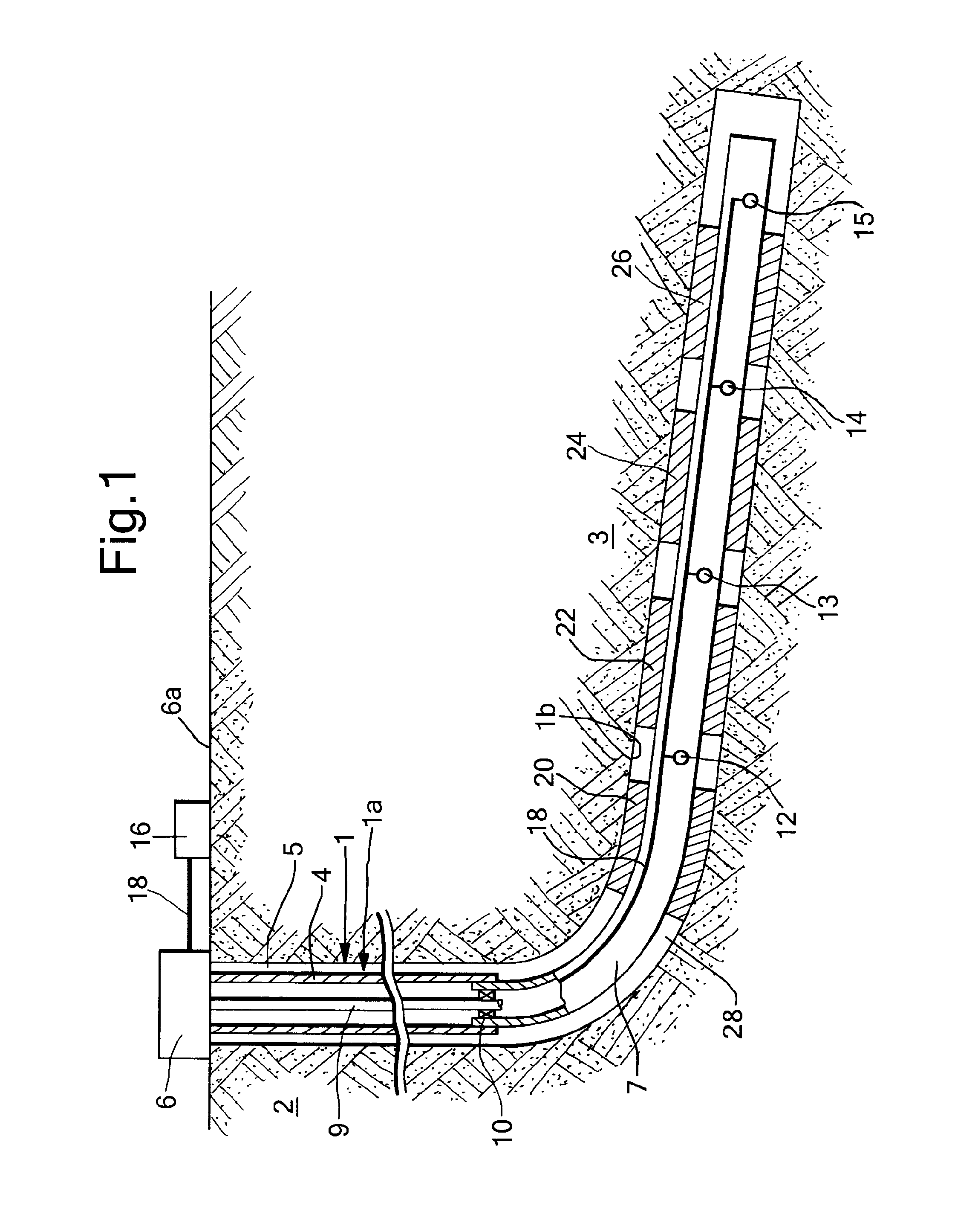
[0021]Referring to FIG. 1 there is shown a wellbore 1 formed in an earth formation 2 for the production of hydrocarbon fluid, the wellbore 1 having a substantially vertical upper section 1a and a substantially horizontal lower section 1b extending into a zone 3 of the earth formation from which hydrocarbon fluid is to be produced. The earth formation zone 3 is fractured whereby there is a risk that water from other formation zones (not shown) enters the lower wellbore section 1b via fractures in formation zone 3. The upper wellbore section 1a is provided with a casing 4 cemented in the wellbore by a layer of cement 5, said casing 4 extending to a wellhead 6 at surface 6a. A production liner 7 extends from the lower end part of the casing 4 into the substantially horizontal wellbore section 1b. A production tubing 9 provides fluid communication between the wellhead 6 and the production liner 7, whereby the production tubing 9 is sealed to the production liner 7 by a packer 10.

[0022]p...


PUM


Abstract

A method is disclosed of creating an annular seal around a tubular element for use in a wellbore. The method comprises providing at least one seal layer of a flexible sealing material susceptible to swelling upon contact with a selected fluid, the seal layer having a first edge and a second edge, and helically winding each seal layer around the tubular element so that the first and second edges extend opposite each other along the tubular element and so that the first and second edges seal relative to each other upon swelling of the flexible sealing material. The tubular element is lowered into the wellbore, and the selected fluid is allowed to contact each seal layer so as to induce swelling of the flexible sealing material whereby the first and second edges seal relative to each other.

Description

RELATED APPLICATIONS[0001]The present application claims priority from PCT / EP2008 / 060793, filed 18 Aug. 2008, which claims priority from European Patent Application 07114621.1 filed 20 Aug. 2007.TECHNICAL FIELD OF THE INVENTION[0002]The present invention relates to a method of creating an annular seal around a tubular element for use in a wellbore.BACKGROUND OF THE INVENTION[0003]In the field of hydrocarbon fluid production from a wellbore it is general practice to seal an annular space formed between an inner tubular wall and an outer tubular wall, such as between a production conduit and a surrounding casing, or between a casing and the wellbore wall. Various types of packers have been applied to provide such sealing functionality. Conventional packers generally are pre-fitted to tubular sections, often referred to as “subs”, which are assembled to form the tubular element. Thus, during assembly of the tubular element it will be required to position the tubular sections provided w...

Claims


Application Information

Patent Timeline
Patent Type & Authority Patents(United States)
IPC IPC(8): E21B33/12
CPCE21B33/1208
Inventor CORNELISSEN, ERIK KERSTDIJKSTRA, NOULINEOUWERKERK, PAUL
Owner SHELL OIL CO
Why Eureka
Try Eureka