Rotating electrical machine

a technology of rotating electrical machines and rotating shafts, which is applied in the direction of rotating parts of magnetic circuits, magnetic circuit shapes/forms/construction, cooling/ventilation arrangements, etc., can solve the problems of field magnetic flux not being changed in accordance, and field magnetic flux being generated, so as to facilitate winding of stators and change field magnetic flux

Inactive Publication Date: 2010-04-20
HITACHI LTD
View PDF14 Cites 9 Cited by
  • Summary
  • Abstract
  • Description
  • Claims
  • Application Information

AI Technical Summary

Benefits of technology

[0007]It is an object of the present invention to provide a rotating electrical machine in which a stator winding can be easily wound around the stator core.
[0011]According to the rotating electrical machine of the present invention, since the stator winding is annularly wound, it is possible to easily wind the stator winding. Since the rotor includes a field winding, the field magnetic flux can be changed.

Problems solved by technology

However, according to the Japanese Patent Application Laid-open No. 2004-15998, since a permanent magnet is used in the rotor for forming a magnetic pole, the field magnetic flux can not be changed in accordance with the revolution number.
Therefore, there is a problem that the field magnetic flux is generated even when it is not required.

Method used


Image

  • Rotating electrical machine
  • Rotating electrical machine
  • Rotating electrical machine

Examples


first embodiment

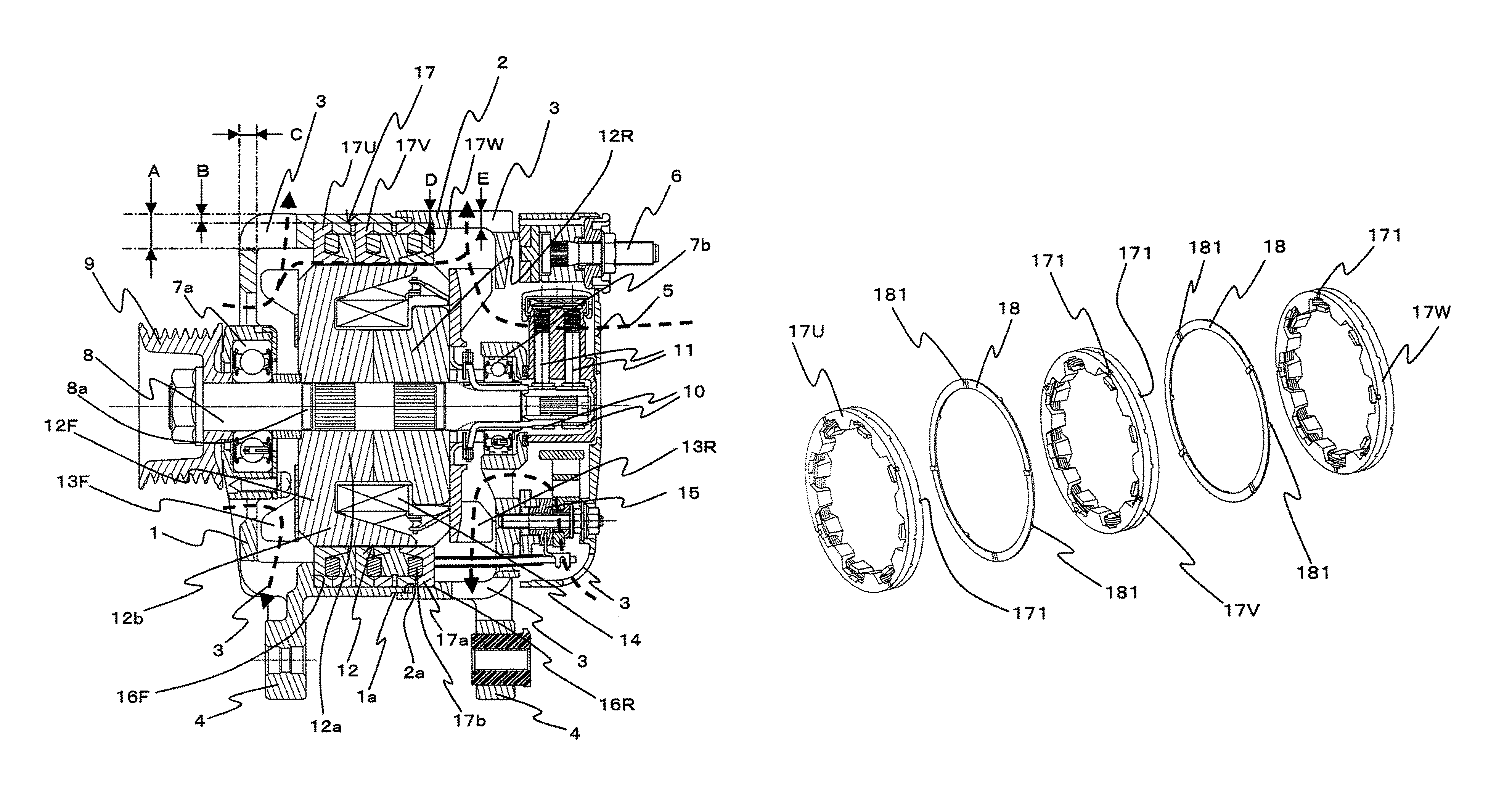
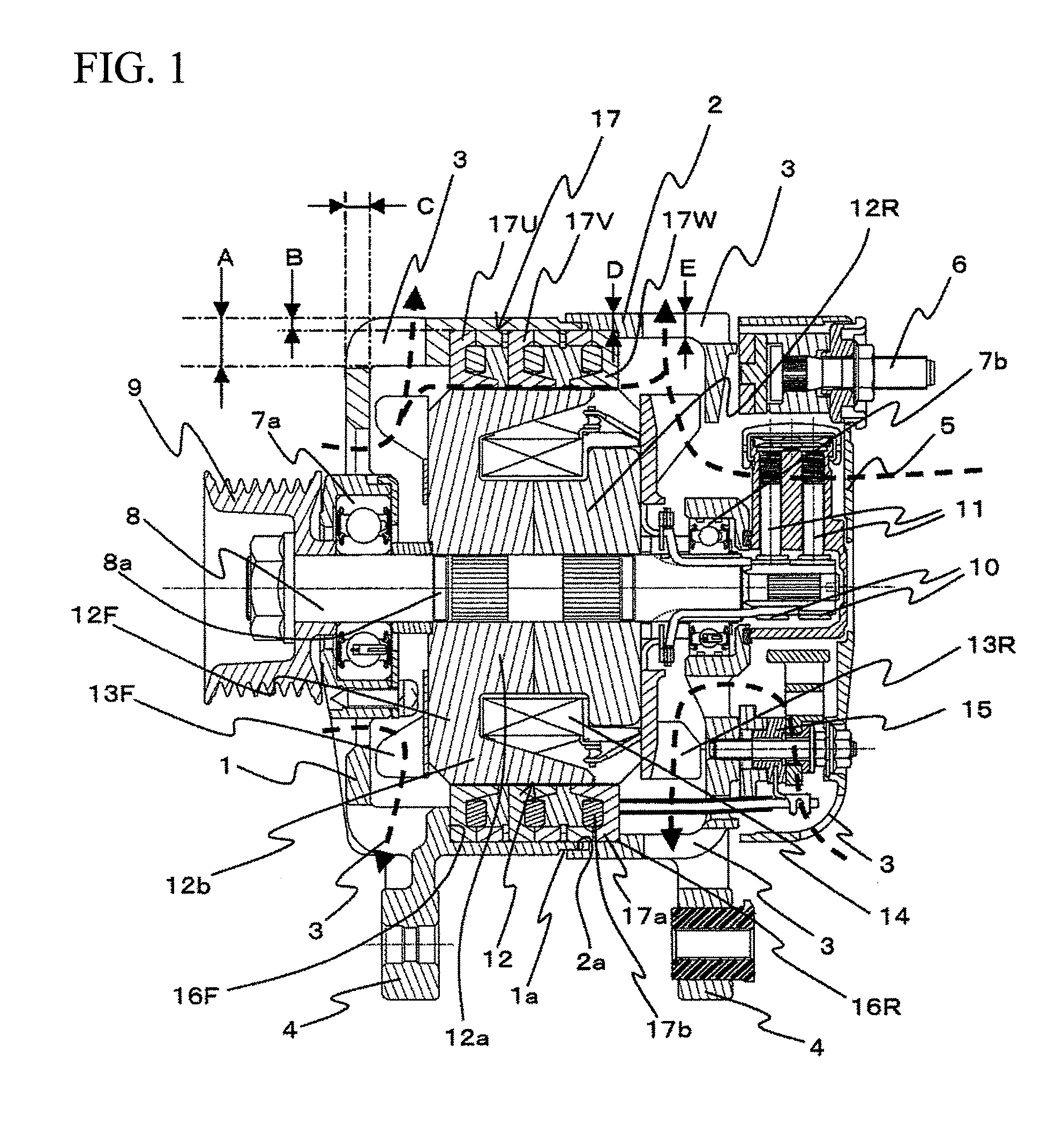
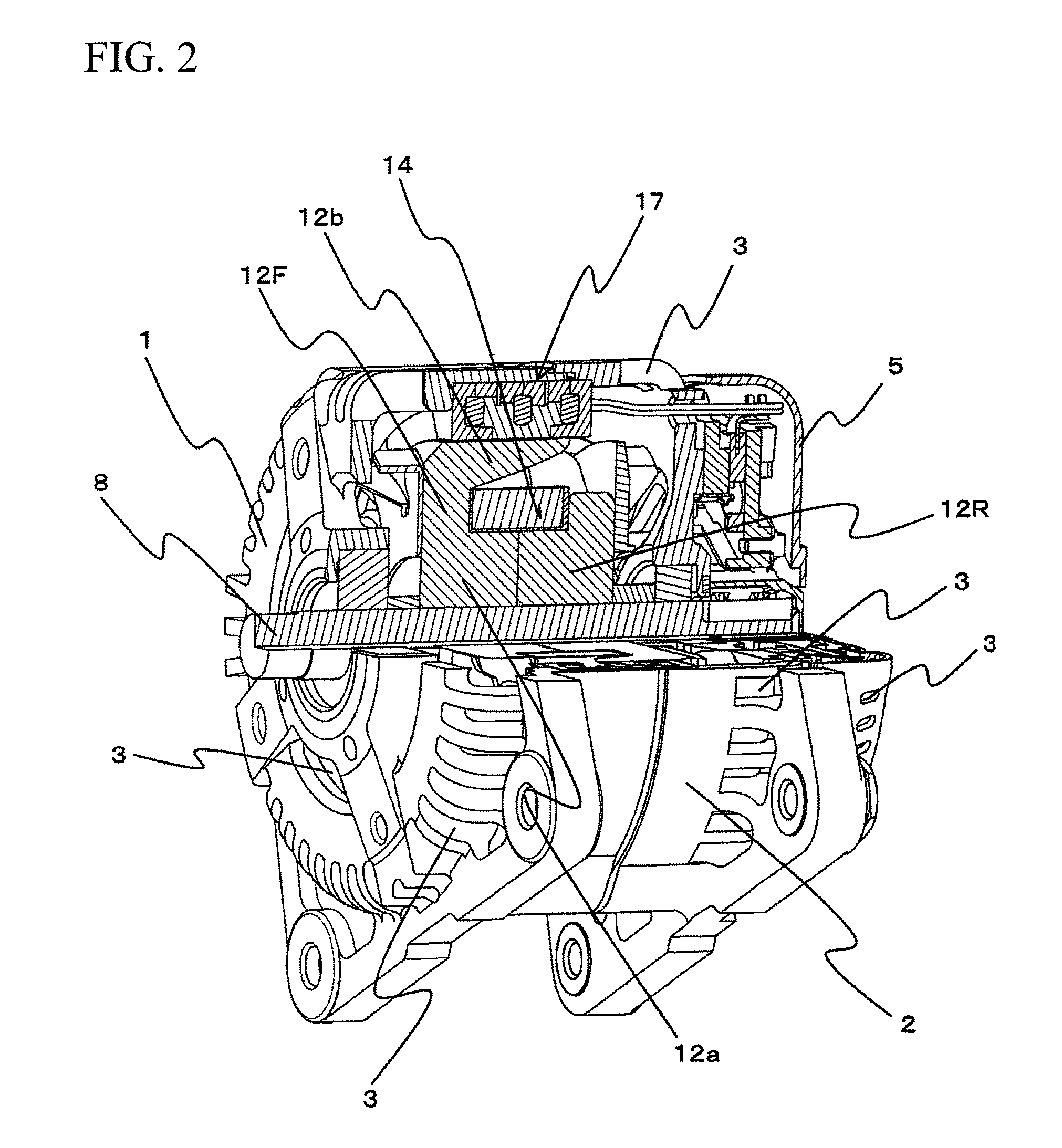
[0037]A vehicular AC power generator which is one embodiment of the rotating electrical machine according to the present invention will be explained based on FIGS. 1 to 7. FIG. 1 is a side sectional view of the vehicular AC power generator. FIG. 2 is a partially cross sectional perspective view of the vehicular AC power generator. FIG. 3 is a partially sectional perspective view of a rotor and a stator. FIG. 4 is a perspective view of the rotor. FIG. 5A is a partially sectional perspective view of the stator only. FIG. 5B is a diagram showing the stator as viewed from its inner peripheral side. FIG. 6 is a perspective view of each phase of the stator. FIG. 7A is a perspective view of the stator from which one of the phases. FIG. 7B is a perspective view of the parts shown in FIG. 7A.

[0038]FIG. 1 shows a vehicular AC power generator of the embodiment. The vehicular AC power generator includes a front bracket 1 disposed on the left side in FIG. 1 and a rear bracket 2 disposed on the l...

second embodiment

[0082]Next, a second embodiment will be explained based on FIGS. 8A and 8B and FIG. 9. FIG. 8A shows output waveform of voltage induced in each phase in the first embodiment. FIG. 8B shows output waveform of voltage induced in each phase in the second embodiment. FIG. 9 is a perspective view showing a rotor and a stator in the second embodiment in section. The same elements as those of the first embodiment are designated with the same name and the same symbols.

[0083]As explained above, in the stator 17 of the first embodiment, the stator cores 17a of the U-phase, the V-phase and the W-phase are disposed adjacent to each other through the connection plates 18. However, even if the phases are connected to each other through the non-magnetic connection plates 18, magnetic flux may leak into the adjacent stator core 17a in some cases. When magnetic flux leaks into the adjacent stator core 17a, magnetic flux leaks into both sides of the stator core 17a of the V-phase disposed between the...

third embodiment

[0089]Next, a third embodiment will be explained based on FIG. 10. FIG. 10 is a perspective view showing a rotor and a stator of the third embodiment in section. The same elements as those of the other embodiments are designated with the same name and the same symbols.

[0090]In the third embodiment, the shape of the permanent magnet 19 is different from that of the second embodiment, but other portions are substantially the same as those in the second embodiment. In the permanent magnet 19 of the third embodiment, a portion corresponding to the V-phase stator 17V is thick so that a cross section in the axial direction assumes substantially T-shape, and portions corresponding to the U-phase stator 17U and the W-phase stator 17W are thin.

[0091]Therefore, in the V-phase stator 17V, the leakage magnetic flux between the rotor pawl magnetic poles 12b is reduced as compared with other phases, and the leakage magnetic flux is increased as compared with the V-phase stator 17V. However, the l...


PUM


Abstract

It is an object of the present invention to make it possible to easily wind a stator winding, enhance an occupied ratio in a stator core, reduce a winding resistance because there is no coil end, and change a field magnetic flux in accordance with a use.Stator pawl magnetic poles of a stator core extend from both sides in an axial direction alternately at locations opposed to a rotor to form a plurality of magnetic poles. With this stator core, it is only necessary to annularly wind a stator winding. Therefore, it is possible to enhance operability and an occupied ratio, and since there is no coil end, it is possible to reduce winding resistance. Since the rotor is a Randall type rotor having a field winding and a rotor pawl magnetic pole, it is possible to change the field magnetic flux in accordance with a use.

Description

BACKGROUND OF THE INVENTION[0001]1. Field of the Invention[0002]The present invention relates to a rotating electrical machine such as a power generator and a motor.[0003]2. Description of the Related Art[0004]A general stator used for a power generator or a motor includes a stator core having an inner peripheral surface from which a plurality of slots are opened in a circumferential direction, and a plurality of stator windings which are respectively wound around the slots. Thus, there are problems that an operation for winding the stator winding into the slot having a narrow width, the operability is inferior and a ratio of an area of the stator winding occupying in the slot can not be increased.[0005]Hence, as shown in Japanese Patent Application Laid-open No. 2004-15998, there is proposed a rotating electrical machine in which the stator core includes stator pawl magnetic poles alternately extending from axially both sides of a portion of the stator opposed to the rotor, and a s...

Claims


Application Information

Patent Timeline
Patent Type & Authority Patents(United States)
IPC IPC(8): H02K1/14
CPCH02K1/145H02K1/243H02K19/22H02K2201/06H02K9/06
Inventor ISHIKAWA, TOSHIOYABUKI, MINORUKANAZAWA, HIROSHIENOMOTO, YUJIISHIKAWA, YOSHIHISA
Owner HITACHI LTD
Why Eureka
Try Eureka