Winding or rewinding machine for producing rolls of web material around a winding spindle and relative winding method

a technology of winding spindle and winding spindle, which is applied in the direction of webs handling, article delivery, thin material handling, etc., can solve the problems of inability to meet the requirements of winding spindle rotation, inability to wind or rewind, and inability to meet the requirements of the various mechanical parts of the machine and its products. to achieve the effect of easily and securely winding around the winding spindl

Inactive Publication Date: 2004-07-29
A CELLI NONWOVENS
View PDF9 Cites 9 Cited by
  • Summary
  • Abstract
  • Description
  • Claims
  • Application Information

AI Technical Summary

Benefits of technology

0017] The object of the present invention is to produce a winding or rewinding machine which does not have the aforesaid disadvantages and allows each roll to be initially wound around the winding spindle easily and securely, by using electrostatic systems to make the initial free end of the web material adhere to the winding spindle, or to the winding cores present on the spindle.

Problems solved by technology

The presence of adhesive in winding or rewinding machines represents a considerable disadvantage as, in addition to the costs deriving from the consumption of adhesive, it inevitably soils the various mechanical parts of the machine and its products.
The presence of adhesive is unacceptable in some types of reels, such as those destined for producing hygiene articles such as medical products, diapers and sanitary towels.
In the first place, the use of jets of air requires the presence of nozzles and a compressed air line, with the consequent plant layout cost and cost deriving from power consumption to supply the compressed air.
The use of compressed air increases the noise of machines and, moreover, does not guarantee reliable and regular start of winding.
In particular, when several strips of web material are wound in parallel on aligned tubular cores, the use of compressed air may cause the head of the strips to veer to the side, thus causing them to overlap with the consequent problems during production.
In peripheral type rewinding or winding machines the application of this technology is more difficult, for the reasons set forth below.
When the winding or rewinding machine is constructed so as to present one or more rollers in contact with the spindle in the initial phase to form a new roll, there is the risk of the web material not being wound correctly around the spindle.
This causes a waste of material and considerably long machine idle times with consequent loss of production.

Method used


Image

  • Winding or rewinding machine for producing rolls of web material around a winding spindle and relative winding method
  • Winding or rewinding machine for producing rolls of web material around a winding spindle and relative winding method
  • Winding or rewinding machine for producing rolls of web material around a winding spindle and relative winding method

Examples


Embodiment Construction

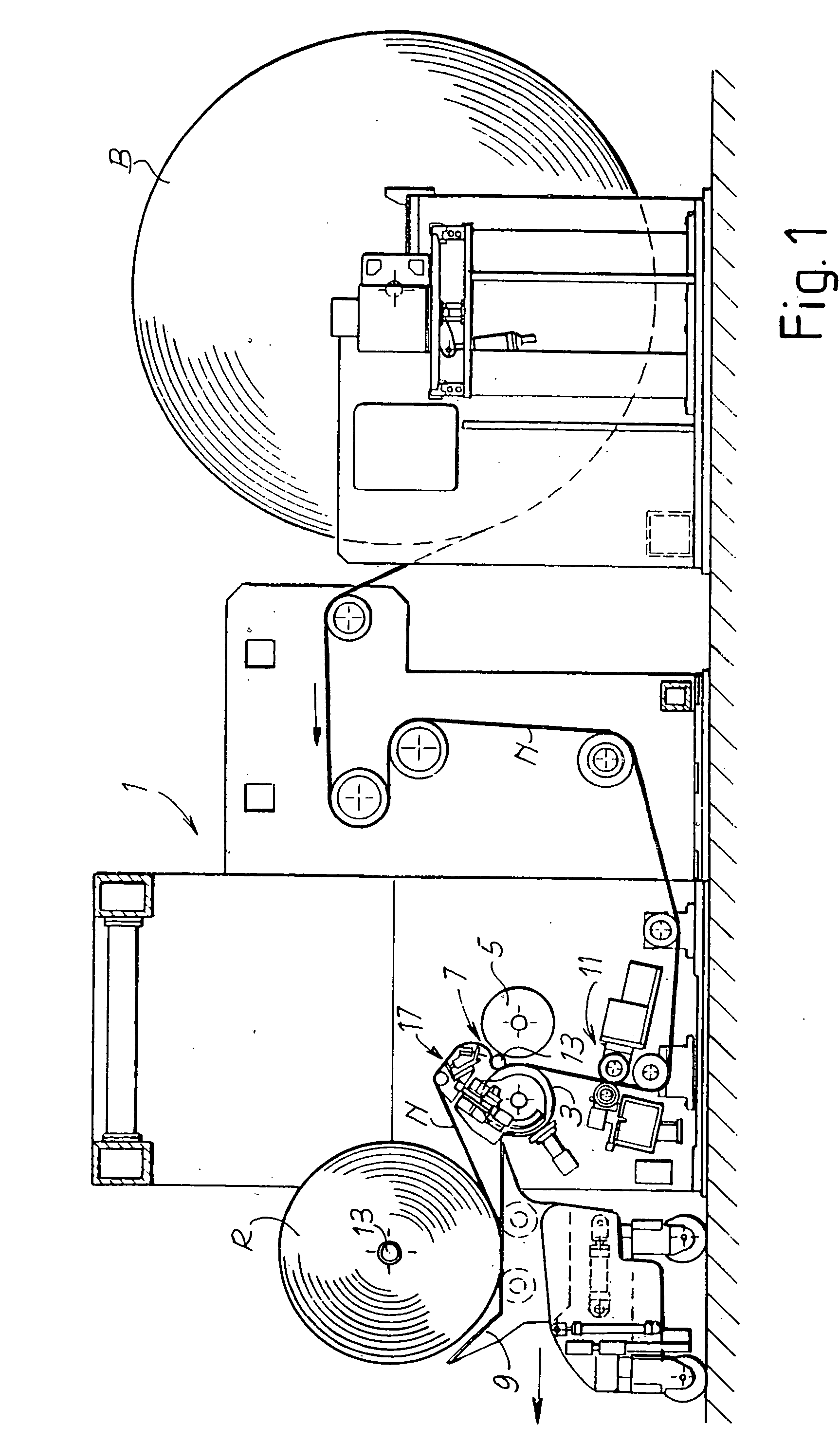
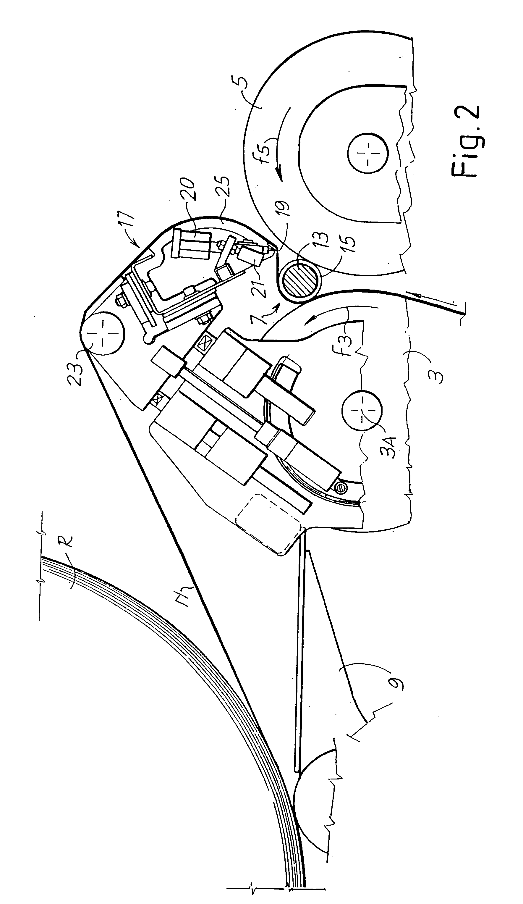
[0044] FIGS. 1 and 2 show a first application of the underlying concept of the invention to a so-called rewinding machine and more specifically a peripheral rewinding machine of the start-stop type.

[0045] The rewinding machine, generically indicated with 1, receives from a reel with a large diameter, indicated with B, a web material N which is rewound on rolls with a smaller diameter, indicated with R. The rewinding machine comprises two winding rollers 3, 5 which define a winding cradle 7, in which the rolls R are formed. After these rolls have been formed they are unloaded onto a carriage indicated with 9, which picks up each roll and transfers it towards an unloading zone. The web material N is fed into the winding cradle passing through a nip between the two winding rollers 3, 5, under which, in a per se known manner, an assembly of cutting blades 11 are positioned to divide the web material N into individual longitudinal strips, each of which is wound onto a respective core mad...


PUM

PropertyMeasurementUnit
voltageaaaaaaaaaa
electrostatically chargeaaaaaaaaaa
non-electrically conductiveaaaaaaaaaa

Abstract

A winding or rewinding machine to wind a web material (N) and form a roll (R) around a winding spindle (13) is disclosed, comprising: at least a roller (5) in contact with said winding spindle in the initial phase of winding the web material around the spindle; a transverse cutting element (19) to cut the web material when a roll has been wound and form an initial free end to wind a subsequent roll around a new winding spindle. Moreover, at least an electrostatic bar (21) to electrostatically charge the web material is also provided. The roller (5) in contact with the spindle is made at least partially in non-electrically conductive material.

Description

[0001] The present invention relates to a machine for producing rolls of web material wound around winding spindles.[0002] Machines of this type are used for example to produce rolls or reels of paper, tissue-paper, non-woven fabric and other web or sheet material.[0003] Winding machine is usually intended as a machine which receives the web material from a production machine upstream and winds it to form a roll or reel of large diameter. Rewinding machine is usually intended as a machine which receives web material from a roll or reel with a large diameter and rewinds it into rolls of a smaller diameter. In both cases the web material may be cut longitudinally in continuous strips, with which several rolls are formed in parallel simultaneously on the same spindle. The term roll or reel is intended, in the context of this document, both as a whole roll or reel and as a series of coaxial rolls placed side by side on the same winding spindle.[0004] Unless otherwise specified, spindle ...

Claims


Application Information

Patent Timeline
Patent Type & Authority Applications(United States)
IPC IPC(8): B65H19/22B65H19/28B65H75/10
CPCB65H19/2238B65H19/28B65H2301/41421B65H2408/236B65H2301/41734B65H2405/422B65H2301/4148
Inventor ACCIARI, GIUSEPPE
Owner A CELLI NONWOVENS
Why Eureka
Try Eureka