Super-endurance solid-state drive with endurance translation layer (ETL) and diversion of temp files for reduced flash wear
What is Al technical title?
Al technical title is built by PatSnap Al team. It summarizes the technical point description of the patent document.
a solid-state drive, endurance technology, applied in the direction of memory adressing/allocation/relocation, instruments, digital storage, etc., can solve the problems of electrons leaking or trapping into the floating gate, thin oxides are more susceptible to trapped charges, and sometimes fail more easily,
Active Publication Date: 2015-02-17
SUPER TALENT TECH CORP
View PDF12 Cites 48 Cited by
Summary
Abstract
Description
Claims
Application Information
AI Technical Summary
This helps you quickly interpret patents by identifying the three key elements:
Problems solved by technology
Method used
Benefits of technology
Problems solved by technology
Unfortunately, some electrons may be trapped in the thin oxide during program or erase.
The thinner oxides are more susceptible to trapped charges and sometimes fail more easily.
Due to program / read interference the electrons can leak or trap into the floating gate.
However, the smaller flash cells have experienced a disturbingly higher wear and newer flash memories may be spec'ed at less than 10,000 program-erase cycles for two-level cells and about 600 for Triple-Level Cells (TLC).
If current trends continue, future flash memories may only allow for 300 program-erase cycles.
Such a low endurance could severely limit the applications that flash memory could be used for, and have severe impacts for Solid-State-Disk (SSD) applications.
However, the noise margins are reduced for the multi-level-cell (MLC) and TLC flash technologies and endurance problems are exacerbated.
It is expected that the underlying flash technology will have lower and lower endurance in the future.
Method used
Image
Click on the blue label to locate the original text in one second.
Reading with bidirectional positioning of images and text.
Examples
Embodiment Construction
[0040]The present invention relates to an improvement in flash-memory drive endurance. The following description is presented to enable one of ordinary skill in the art to make and use the invention as provided in the context of a particular application and its requirements. Various modifications to the preferred embodiment will be apparent to those with skill in the art, and the general principles defined herein may be applied to other embodiments. Therefore, the present invention is not intended to be limited to the particular embodiments shown and described, but is to be accorded the widest scope consistent with the principles and novel features herein disclosed.
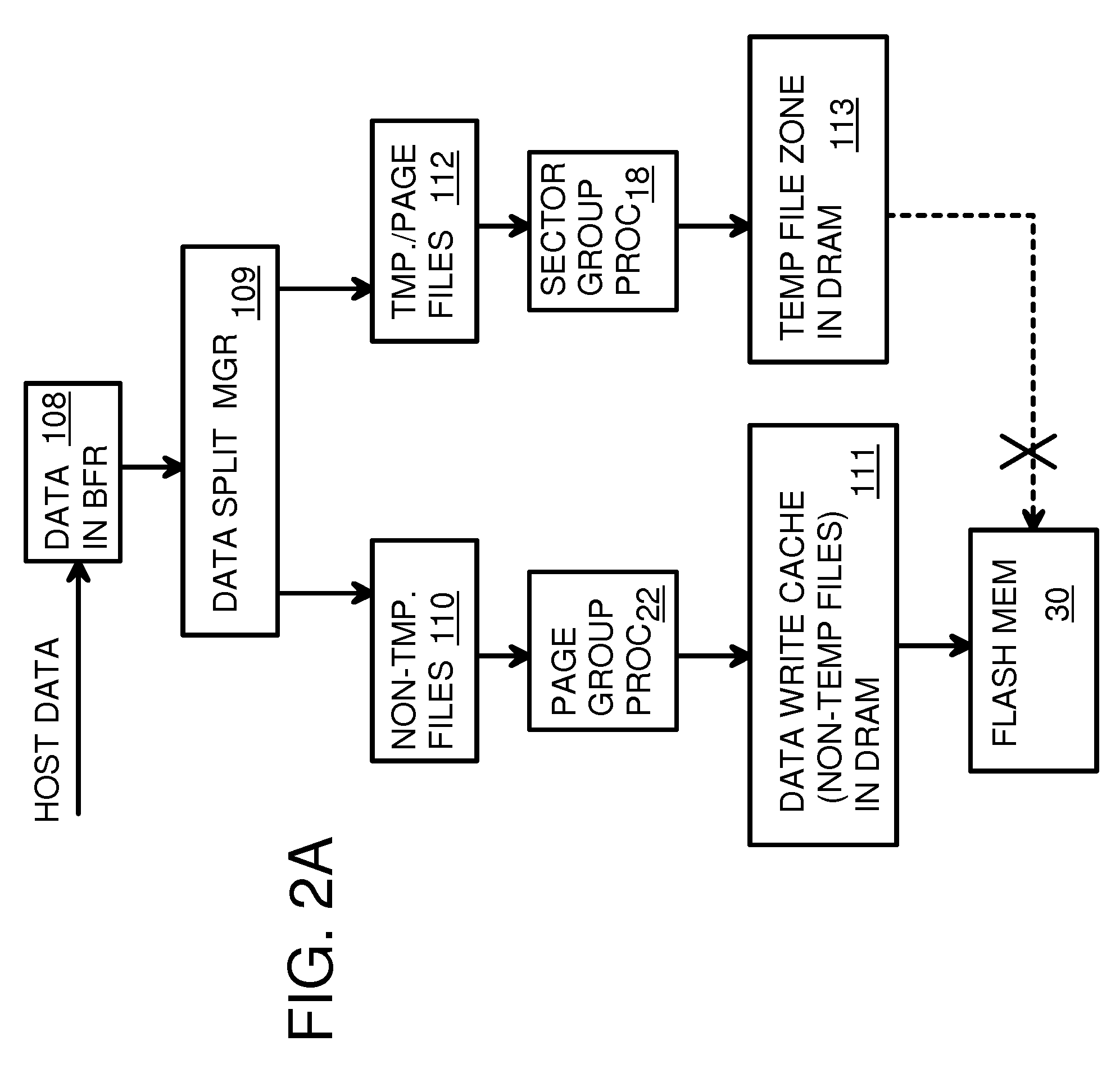
[0041]The wear on underlying flash devices may be reduced by blocking unnecessary writes to the flash memory. A DRAM buffer in the flash drive can store data that does not need to be stored permanently and thus does not need to be written to flash. The DRAM is not only faster, it can be over-written more than one million ...
PUM
Abstract
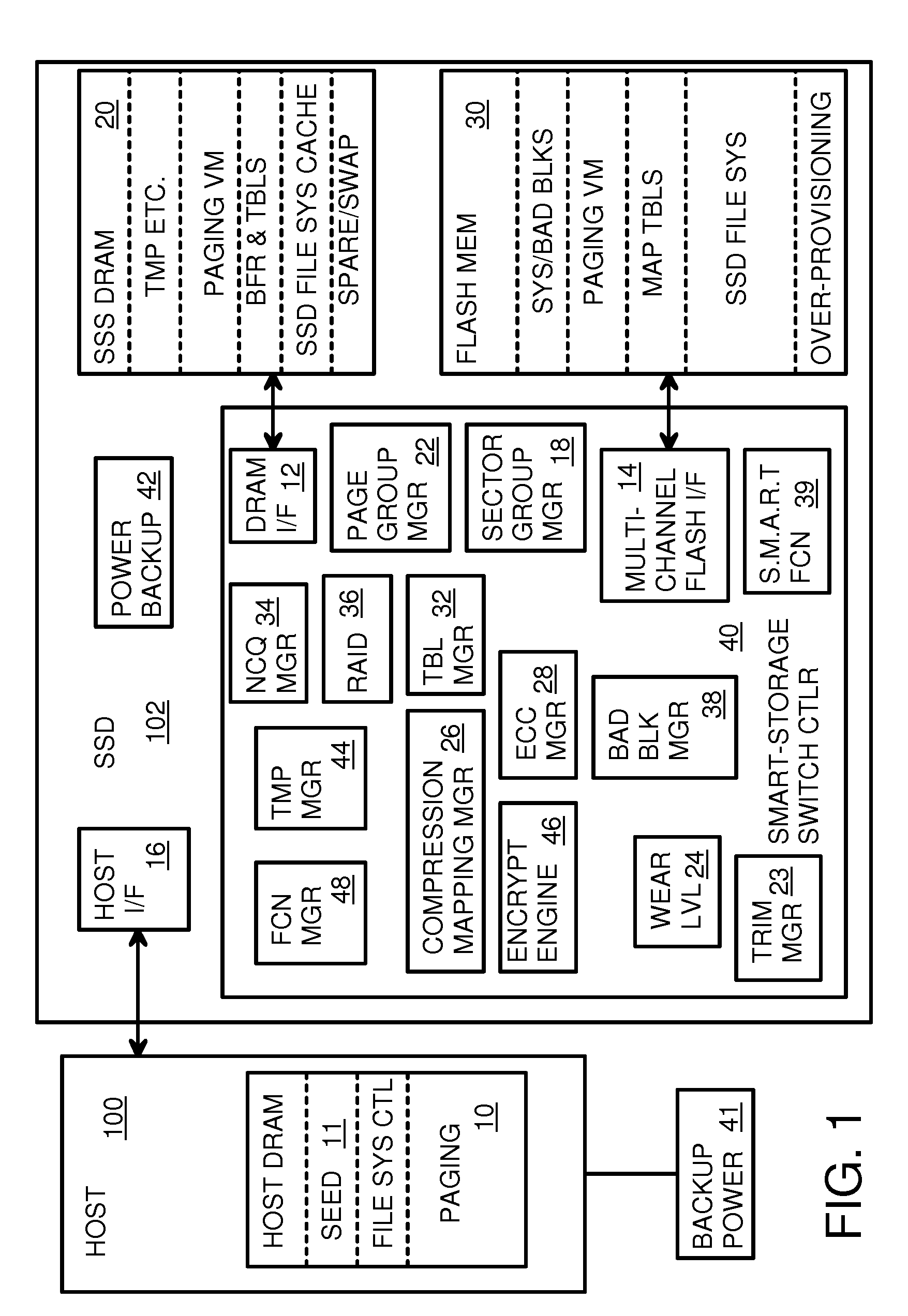
A flash drive has increased endurance and longevity by reducing writes to flash. An Endurance Translation Layer (ETL) is created in a DRAM buffer and provides temporary storage to reduce flash wear. A Smart Storage Switch (SSS) controller assigns data-type bits when categorizing host accesses as paging files used by memory management, temporary files, File Allocation Table (FAT) and File Descriptor Block (FDB) entries, and user data files, using address ranges and file extensions read from FAT. Paging files and temporary files are never written to flash. Partial-page data is packed and sector mapped by sub-sector mapping tables that are pointed to by a unified mapping table that stores the data-type bits and pointers to data or tables in DRAM. Partial sectors are packed together to reduce DRAM usage and flash wear. A spare / swap area in DRAM reduces flash wear. Reference voltages are adjusted when error correction fails.
Description
RELATED APPLICATIONS[0001]This application is a continuation-in-part (CIP) of “Multi-Level Striping and Truncation Channel-Equalization for Flash-Memory System”, U.S. Ser. No. 12 / 475,457, filed on May 29, 2009.[0002]This application is a continuation-in-part of “Swappable Sets of Partial-Mapping Tables in a Flash-Memory System With A Command Queue for Combining Flash Writes”, Ser. No. 12 / 347,306, filed on Dec. 31, 2008, now U.S. Pat. No. 8,112,574.[0003]This application is a continuation-in-part of “High Performance and Endurance Non-volatile Memory Based Storage Systems”, U.S. Ser. No. 12 / 141,879, filed Jun. 18, 2008.[0004]This application is related to “High Endurance Non-volatile Memory Devices”, U.S. Pat. No. 7,953,931, filed on Feb. 21, 2008.[0005]This application is related to “Cell-Downgrading and Reference-Voltage Adjustment for a Multi-Bit-Cell Flash Memory”, U.S. Pat. No. 7,333,364, filed on Apr. 19, 2007.FIELD OF THE INVENTION[0006]This invention relates to flash-memory d...
Claims
Application Information
Patent Timeline
Application Date:The date an application was filed.
Publication Date:The date a patent or application was officially published.
First Publication Date:The earliest publication date of a patent with the same application number.
Issue Date:Publication date of the patent grant document.
PCT Entry Date:The Entry date of PCT National Phase.
Estimated Expiry Date:The statutory expiry date of a patent right according to the Patent Law, and it is the longest term of protection that the patent right can achieve without the termination of the patent right due to other reasons(Term extension factor has been taken into account ).
Invalid Date:Actual expiry date is based on effective date or publication date of legal transaction data of invalid patent.