
Systems for chromatic aberration correction in total internal reflection fluorescence microscopy

a technology of total internal reflection and fluorescence microscopy, applied in the field of fluorescence microscopy, can solve the problems of increasing the cost of an objective-based tirf microscope, chromatic aberration in the beam, and several challenges of objective-based tirf microscopes

Inactive Publication Date: 2015-02-24
LEICA MICROSYSTEMS CMS GMBH
View PDF3 Cites 3 Cited by
  • Summary
  • Abstract
  • Description
  • Claims
  • Application Information

AI Technical Summary

Problems solved by technology

On the other hand, objective-based TIRF microscopes present several challenges when dealing with multiple wavelength TIRF.
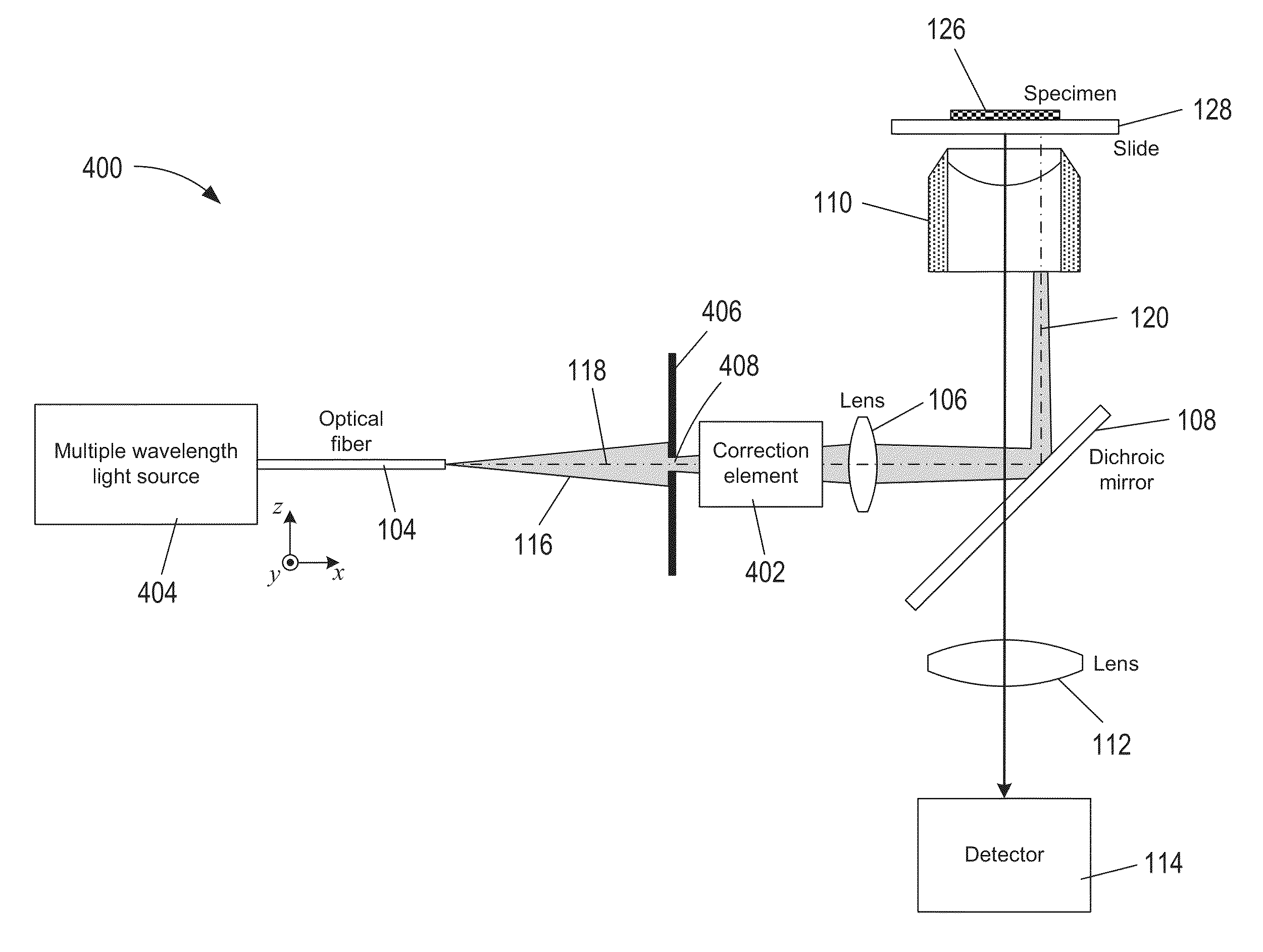
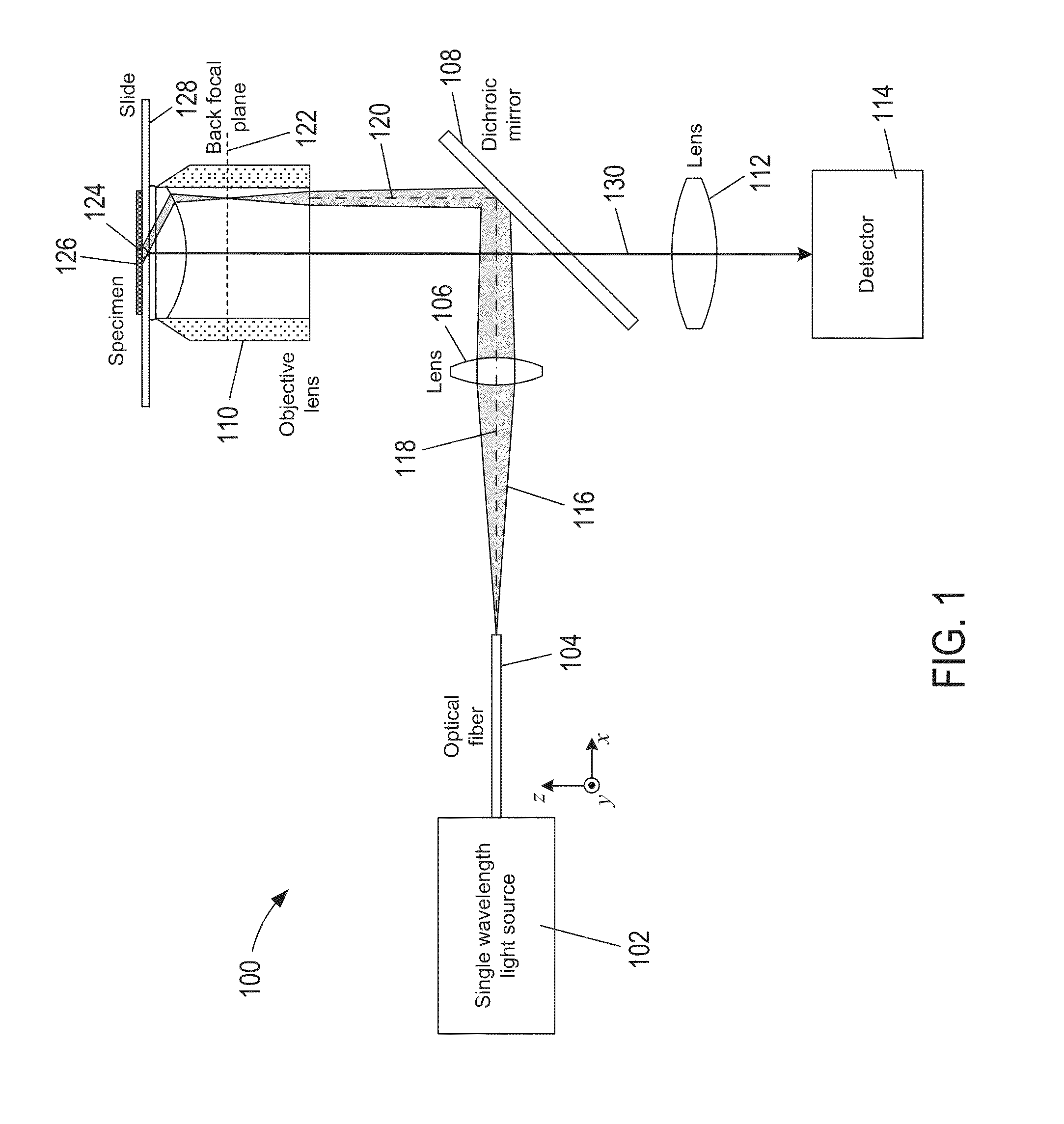
For instance, multiple wavelength TIRF microscopes use a multiple wavelength excitation beam directed along the outer edge of the objective lenses, but the outer edges of the lenses cause chromatic aberrations in the beam.
However, steering and refocusing the beam for each wavelength takes time, prevents simultaneous imaging with more than one wavelength, and requires additional mechanical systems to change the position of the excitation beam source, which increases the cost of an objective-based TIRF microscope.

Method used


Image

  • Systems for chromatic aberration correction in total internal reflection fluorescence microscopy
  • Systems for chromatic aberration correction in total internal reflection fluorescence microscopy
  • Systems for chromatic aberration correction in total internal reflection fluorescence microscopy

Examples


Embodiment Construction

[0023]A general description of two kinds of problems associated with chromatic aberrations created in objective-based total internal reflection fluorescence (“TIRF”) microscopy is presented in a first subsection. A description of various correction elements that can be incorporated into objective-base TIRF microscopy instruments to correct various types of chromatic aberrations is presented in a second subsection.

Two Problems Created by Chromatic Aberrations in Multiple-Wavelength Objective-Based TIRF Microscopy

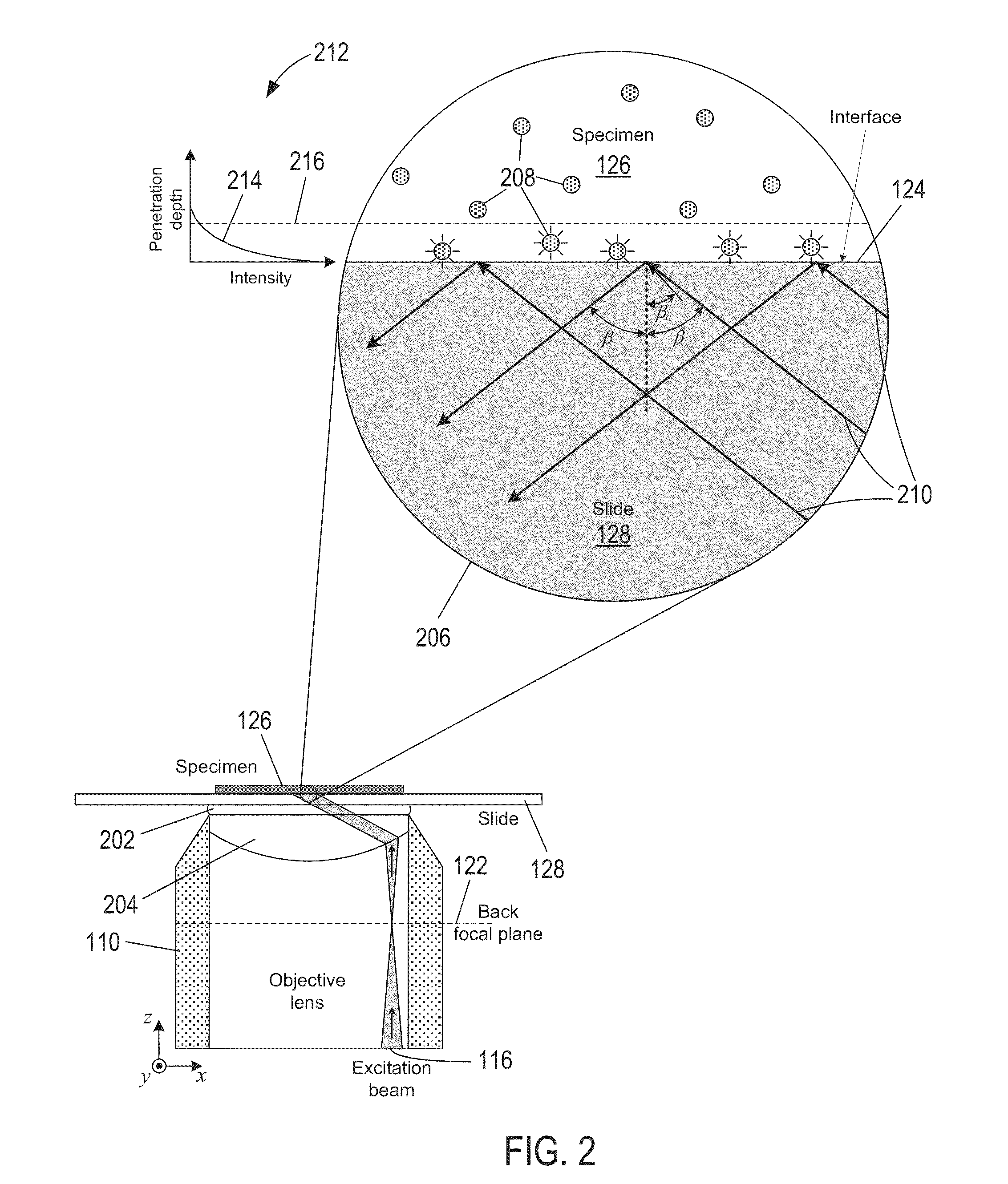
[0024]FIG. 1 shows a schematic representation of an example TIRF microscopy instrument 100 that does not include a correction element. Note that the instrument 100 is not intended to represent all of the various types of TIRF microscopy instruments. There are many different types of TIRF microscopy instruments and corresponding optical paths. Instrument 100 is also not intended to represent the optical paths within all the different, well-known variations of TIRF microscopy i...


PUM


Abstract

Correction elements that can be incorporated in objective-based TIRF microscopy instruments to correct for chromatic aberrations are described. A correction element can be placed between a multiple wavelength excitation beam source and the microscope objective lens. In one aspect, the thickness of the correction element is defined to compensate for different axial positions of the focal points associated with each excitation wavelengths traveling along the outer edge of lenses comprising a microscope objective lens. In another aspect, the correction element can be angled and / or configured so that the different wavelengths of multiple wavelength excitation light are shifted to adjust the angle of incidence for each wavelength at the specimen / substrate interface.

Description

CROSS-REFERENCE TO RELATED APPLICATIONS[0001]This application claims priority to U.S. provisional patent application No. 61 / 432,020 filed Jan. 12, 2011, the disclosure of which is incorporated herein by reference in its entirety.TECHNICAL FIELD[0002]This disclosure relates to fluorescence microscopy and, in particular, to systems that correct chromatic aberrations in total internal reflection fluorescence microscopy.BACKGROUND OF THE INVENTION[0003]Many different techniques have been developed in the field of fluorescence microscopy to restrict excitation light to a thin region of a specimen in order to improve the signal-to-background noise ratio and the spatial resolution of specimen features or components of interest. Total internal reflection fluorescence (“TIRE”) microscopy is a technique in which a beam of excitation light is restricted to a thin region of the specimen adjacent to the interface between the specimen and a transparent substrate, such as a slide, coverslip or dis...

Claims


Application Information

Patent Timeline
Patent Type & Authority Patents(United States)
IPC IPC(8): G02B21/08G02B21/00G02B21/16G02B27/00
CPCG02B21/16G02B27/0025G02B21/0076
Inventor COOPER, JEREMY R.
Owner LEICA MICROSYSTEMS CMS GMBH
Learn More