Systems for fluorescence illumination using superimposed polarization states

Active Publication Date: 2012-07-12
GLOBAL LIFE SCI SOLUTIONS USA LLC
View PDF6 Cites 32 Cited by
  • Summary
  • Abstract
  • Description
  • Claims
  • Application Information

AI Technical Summary

Benefits of technology

[0004]Various superimposing beam controls that can superimpose beams of light with different optical properties are described. In one aspect, a beam control receives a beam of light and outputs one or more beams. Each beam is output with a different polarization state and with different optical properties. Superimposing beam contro

Problems solved by technology

However, steering the excitation beam in this manner limits use of the microscope to only one fluorescenc

Method used


Image

  • Systems for fluorescence illumination using superimposed polarization states
  • Systems for fluorescence illumination using superimposed polarization states
  • Systems for fluorescence illumination using superimposed polarization states

Examples


Embodiment Construction

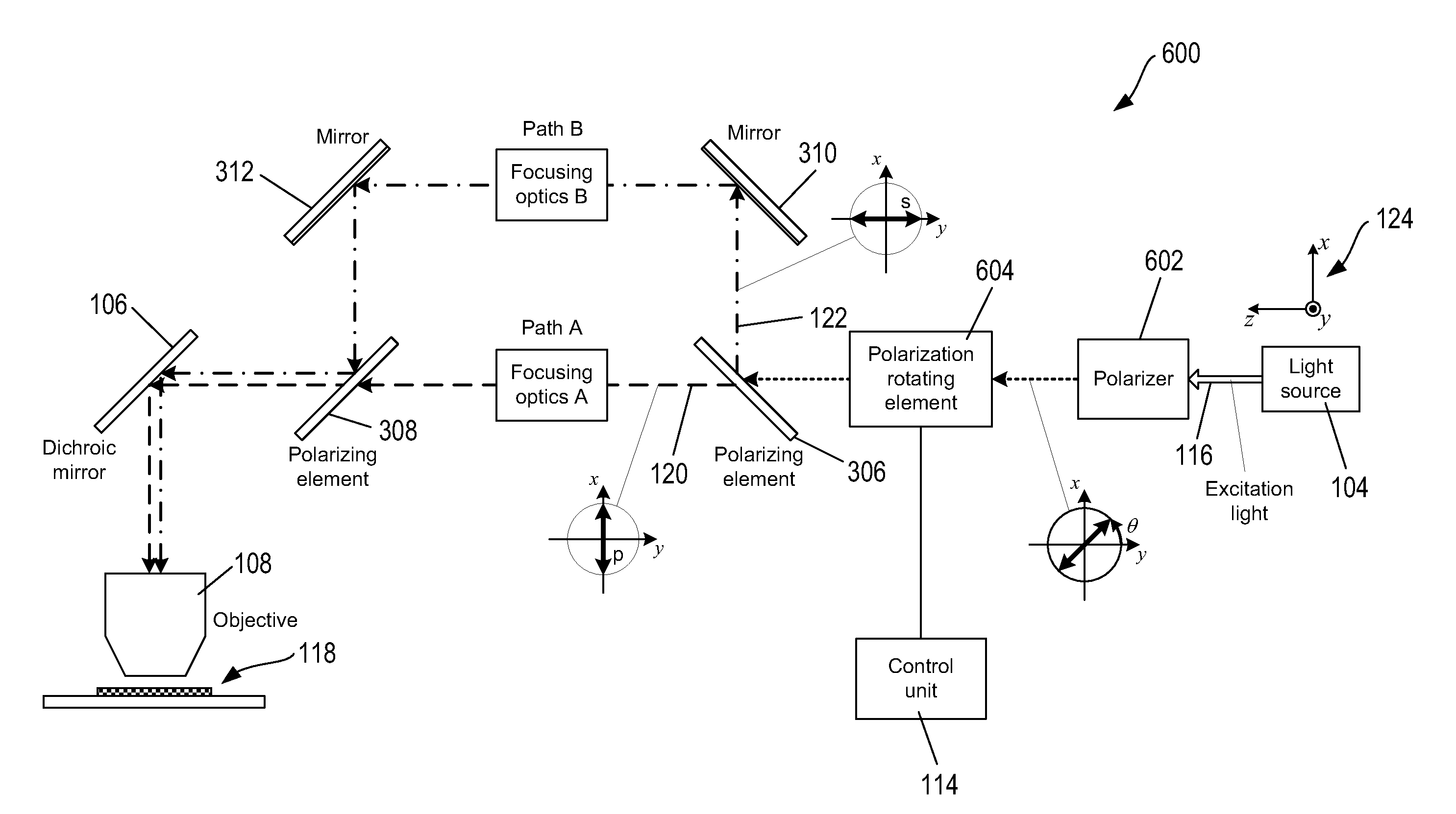
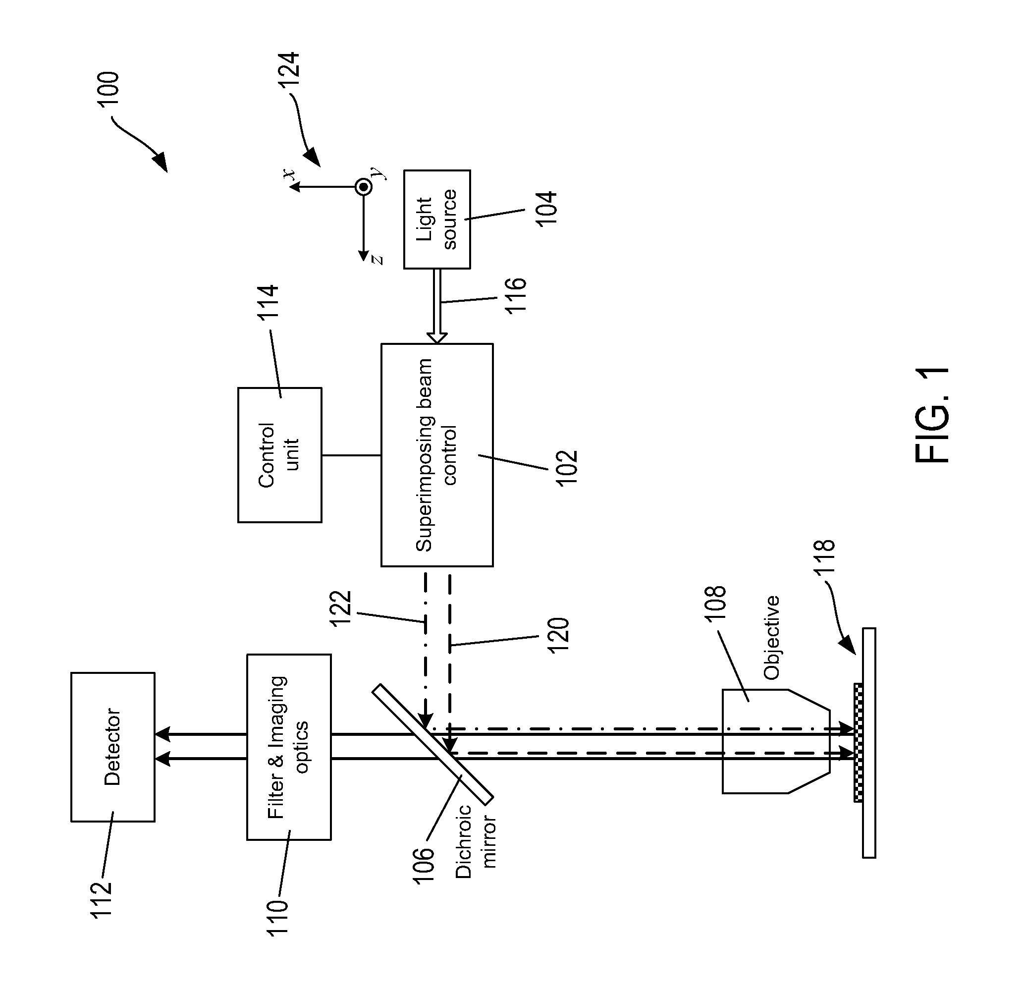
[0014]FIG. 1 shows an example of a fluorescence microscopy instrument 100 that includes a superimposing beam control 102. The instrument 100 also includes a light source 104, a dichroic minor 106, an objective lens 108, filtering and imaging optics 110, a detector 112, and a control unit 114 connected to the beam control 102. The light source 104 can be a laser that emits a high-intensity, substantially monochromatic beam of excitation light 116 selected to stimulate emission of fluorescent light from fluorophores of fluorescent probes that are designed to bind to particular components of a specimen 118. The beam 116 can be linearly polarized with a particular polarization angle and is input to the beam control 102, which splits the excitation beam 116 into a first beam with a first polarization state represented by dashed line directional arrow 120 and a second beam with a second polarization state represented by dot-dashed line directional arrow 122. The dichroic minor 106 is conf...


PUM


Abstract

Various superimposing beam controls that can superimpose beams of light with different optical properties are described. In one aspect, a beam control receives a beam of light and outputs one or more beams. Each beam is output in a different polarization state and with different optical properties. Superimposing beam controls can be incorporated in fluorescence microscopy instruments to split a beam of excitation light into one or more beams of excitation light. Each beam of excitation light has a different polarization and is output with different optical properties so that each excitation beam can be used to execute a different microscopy technique.

Description

CROSS-REFERENCE TO RELATED APPLICATIONS[0001]This application claims the benefit of U.S. provisional application No. 61 / 432,008; filed Jan. 12, 2011.TECHNICAL FIELD[0002]This disclosure relates to fluorescence microscopy and, in particular, to fluorescent microscopy instruments that can use different microscopy techniques to image a specimen.BACKGROUND OF THE INVENTION[0003]Fluorescence microscopy offers a unique approach to the study of living and fixed cells because of its sensitivity, specificity and versatility. Fluorescent light emitted from fluorescent probes attached to components of a specimen can be simultaneously detected as image and photometric data using the microscope, which provides the potential for qualitative and quantitative studies on the structure and function of the components. In recent years, increasingly elaborate fluorescence microscopy techniques, including fluorescence recovery after photobleaching (“FRAP”), fluorescence lifetime imaging microscopy (“FLIM...

Claims


Application Information

Patent Timeline
IPC IPC(8): G02B21/06G02B27/28
CPCG02B27/283G02B21/16G02B21/0092
Inventor COOPER, JEREMY R.
Owner GLOBAL LIFE SCI SOLUTIONS USA LLC
Why Eureka
Try Eureka