Method for manufacturing a surface optical layer

a surface optical layer and manufacturing method technology, applied in the direction of diffusing elements, instruments, synthetic resin layered products, etc., can solve the problems of user discomfort and difficulty in viewing the display, waste of manufacturing funds, consumption of research and development efforts, etc., and achieve the effect of increasing the visibility of the display

Inactive Publication Date: 2005-07-14
OPTIMAX TECHNOLOGY CORPORATION
View PDF3 Cites 1 Cited by
  • Summary
  • Abstract
  • Description
  • Claims
  • Application Information

AI Technical Summary

Benefits of technology

[0007] It is therefore an objective of the present invention to provide an anti-glare film, which is used in a display to scatter light, such that the visibility of the display is increased and the user does not feel uncomfortable while viewing the display.

Problems solved by technology

Additionally, if external light shines on the display surface and is reflected at the user without scattering, the user feels uncomfortable and has difficulty viewing the display.
Consequently, manufacturing finances are wasted, research and development efforts are consumed, preparation time for mass production is lengthened; manufacturing an anti-glare film in this way is uneconomical.

Method used


Image

  • Method for manufacturing a surface optical layer
  • Method for manufacturing a surface optical layer
  • Method for manufacturing a surface optical layer

Examples


Embodiment Construction

[0017] Reference will now be made in detail to the present preferred embodiments of the invention, examples of which are illustrated in the accompanying drawings. Wherever possible, the same reference numbers are used in the drawings and the description to refer to the same or like parts.

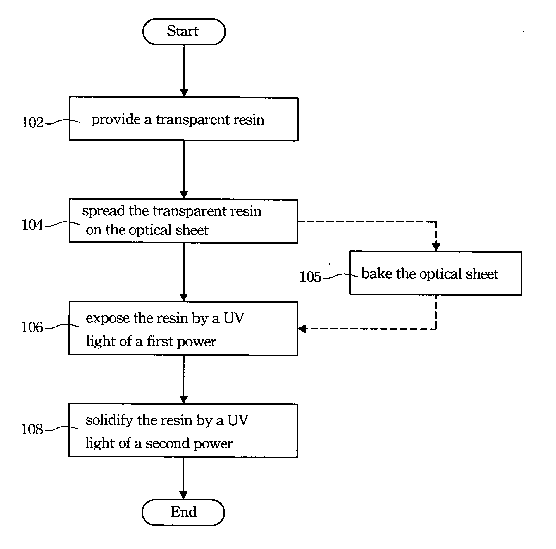
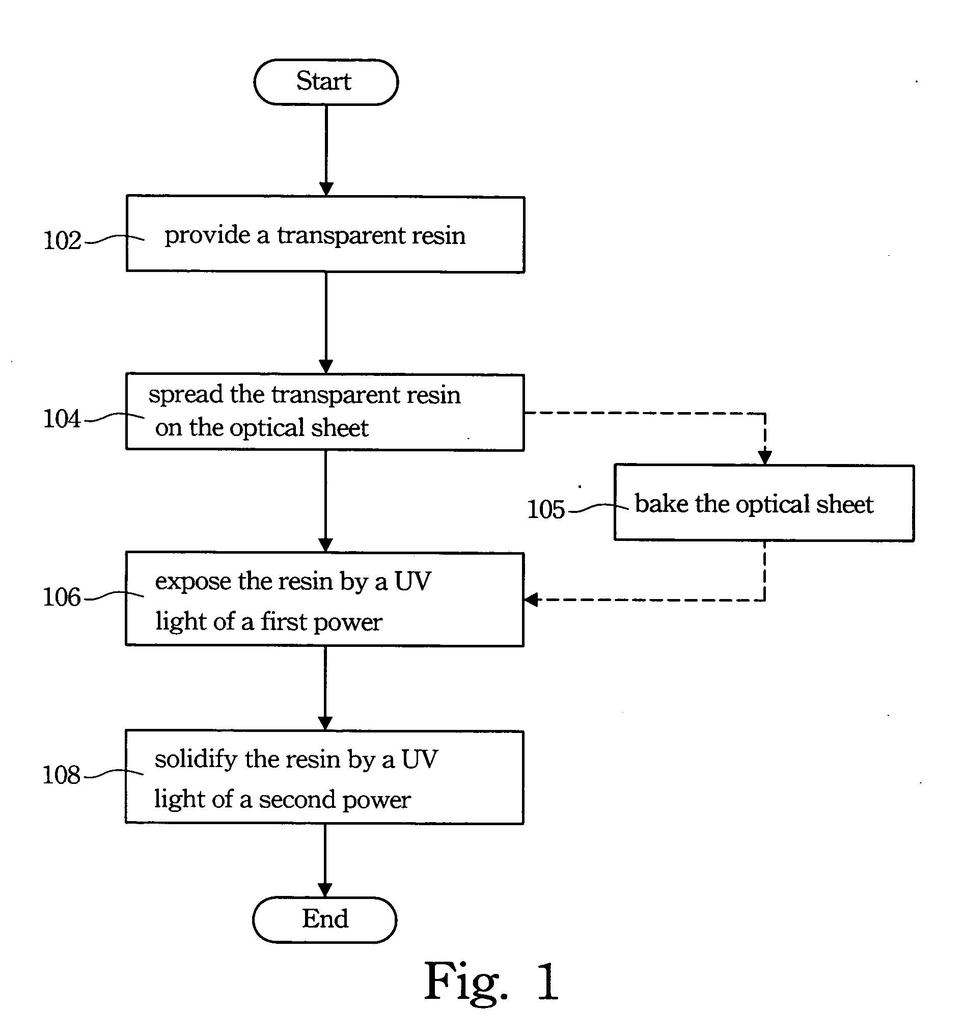
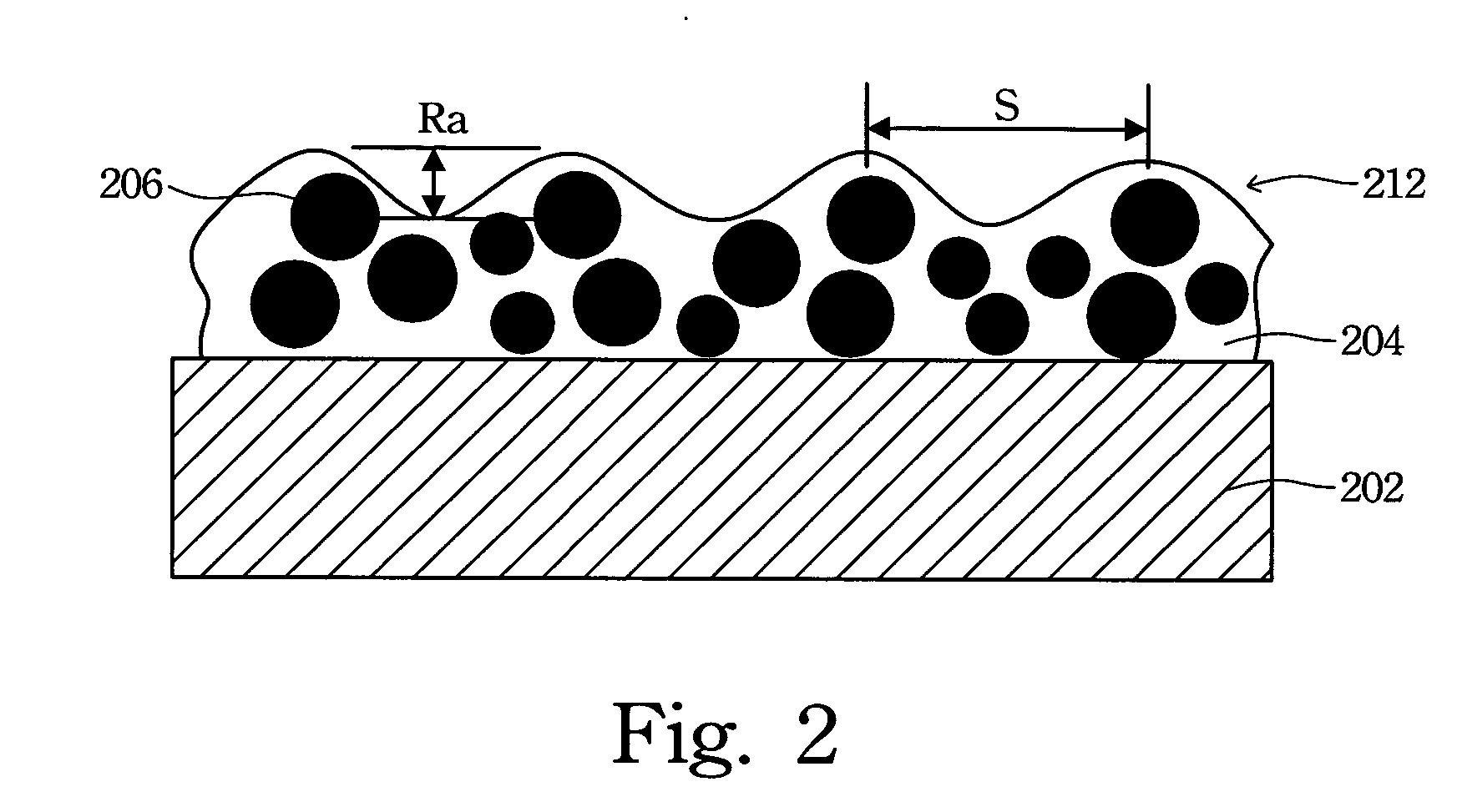
[0018] The invention spreads a transparent resin having a plurality of transparent particles on an optical sheet, and exposes and solidifies the transparent resin by UV light of at least two different powers. When the transparent resin is exposed to UV light of a lower power, the transparent resin is not totally solidified. This step is critical to change the optical properties of the surface optical layer, in which when the exposing time of UV light of the lower power is longer, the resultant haze of the surface optical layer is higher while the transparency of the surface optical layer is kept intact.

[0019] Referring to FIG. 1, a flow chart of one preferred embodiment of the invention is illustr...


PUM

PropertyMeasurementUnit
wavelengthaaaaaaaaaa
transparentaaaaaaaaaa
powersaaaaaaaaaa

Abstract

A transparent resin having a plurality of transparent particles is spread on an optical sheet. The transparent resin is exposed to ultraviolet light of a first power and then cured by ultraviolet light of a second power, which is greater than the first power. Thus, surface optical layers with different optical properties are easily obtained by only adjusting the power of ultraviolet light, without changing the original content of the surface optical layer or the parameters of its spreading process.

Description

BACKGROUND [0001] 1. Field of Invention [0002] The present invention relates to a method for manufacturing an optical element of a display device. More particularly, the present invention relates to a method for manufacturing a surface optical layer. [0003] 2. Description of Related Art [0004] Due to the internal light source of a transmissive display transmitting light outwardly, an anti-glare film is usually coated on the surface of the display to scatter the internal light to prevent the light from being shone too intensely and distractingly on the user. Additionally, if external light shines on the display surface and is reflected at the user without scattering, the user feels uncomfortable and has difficulty viewing the display. Therefore, the anti-glare film must be able to reduce the reflection of external light outside the display as well as scatter internal light originating from inside the display. [0005] Many conventional techniques and patents discuss anti-glare film. Fo...

Claims


Application Information

Patent Timeline
Patent Type & Authority Applications(United States)
IPC IPC(8): G02B5/02B05D3/06B05D5/06B05D7/00B32B27/16G02B1/10G02B1/11G02B1/12G03F7/20
CPCG02B1/12G02B1/11G03F7/20
Inventor HONG, WEI-DUZLI, TUNG-LUNGWU, LUNG-HAILAI, TA-WANG
Owner OPTIMAX TECHNOLOGY CORPORATION
Why Eureka
Try Eureka