Vehicular display device

a technology of display device and projection device, which is applied in the direction of vehicle components, instruments, optics, etc., can solve the problem of not always being able to dispose of the projection device at the desired position, and achieve the effect of improving the degree of freedom in the arrangement of the projection device and improving the visibility of the display imag

Inactive Publication Date: 2021-03-11
YAZAKI CORP
View PDF0 Cites 0 Cited by
  • Summary
  • Abstract
  • Description
  • Claims
  • Application Information

AI Technical Summary

Benefits of technology

[0005]An object of the present invention is to provide a vehicular display device capable of improving the visibility of a display image and improving the degree of freedom in the arrangement of a projection device.

Problems solved by technology

However, since there is a mounting position limitation in the vehicle, it is not always possible to dispose the projection device at a desired position.

Method used


Image

  • Vehicular display device
  • Vehicular display device
  • Vehicular display device

Examples


embodiment

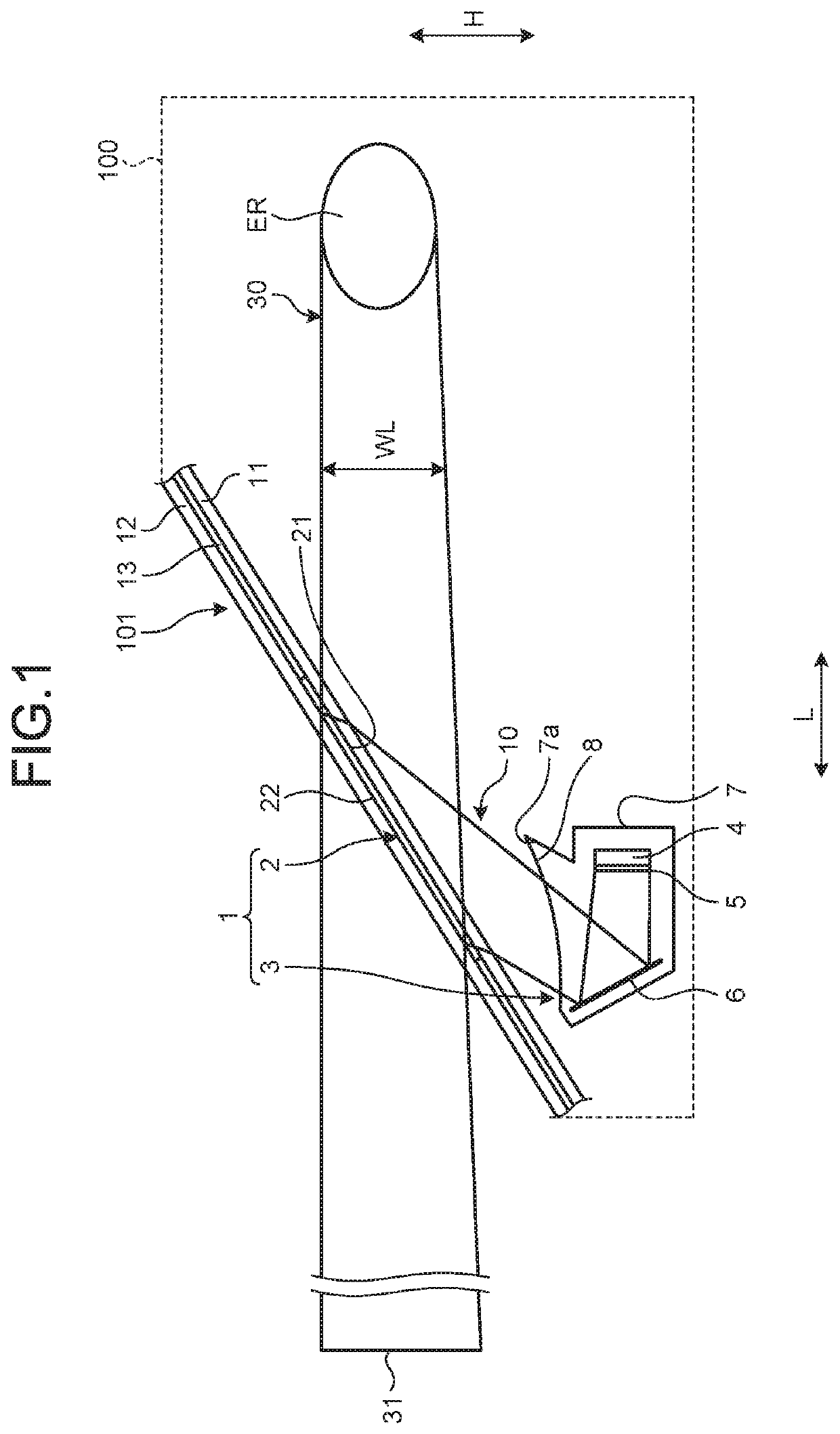
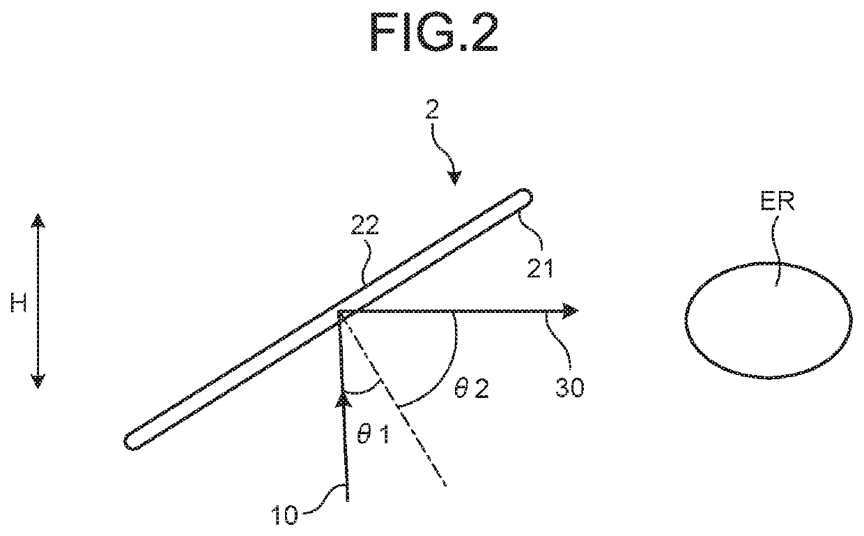
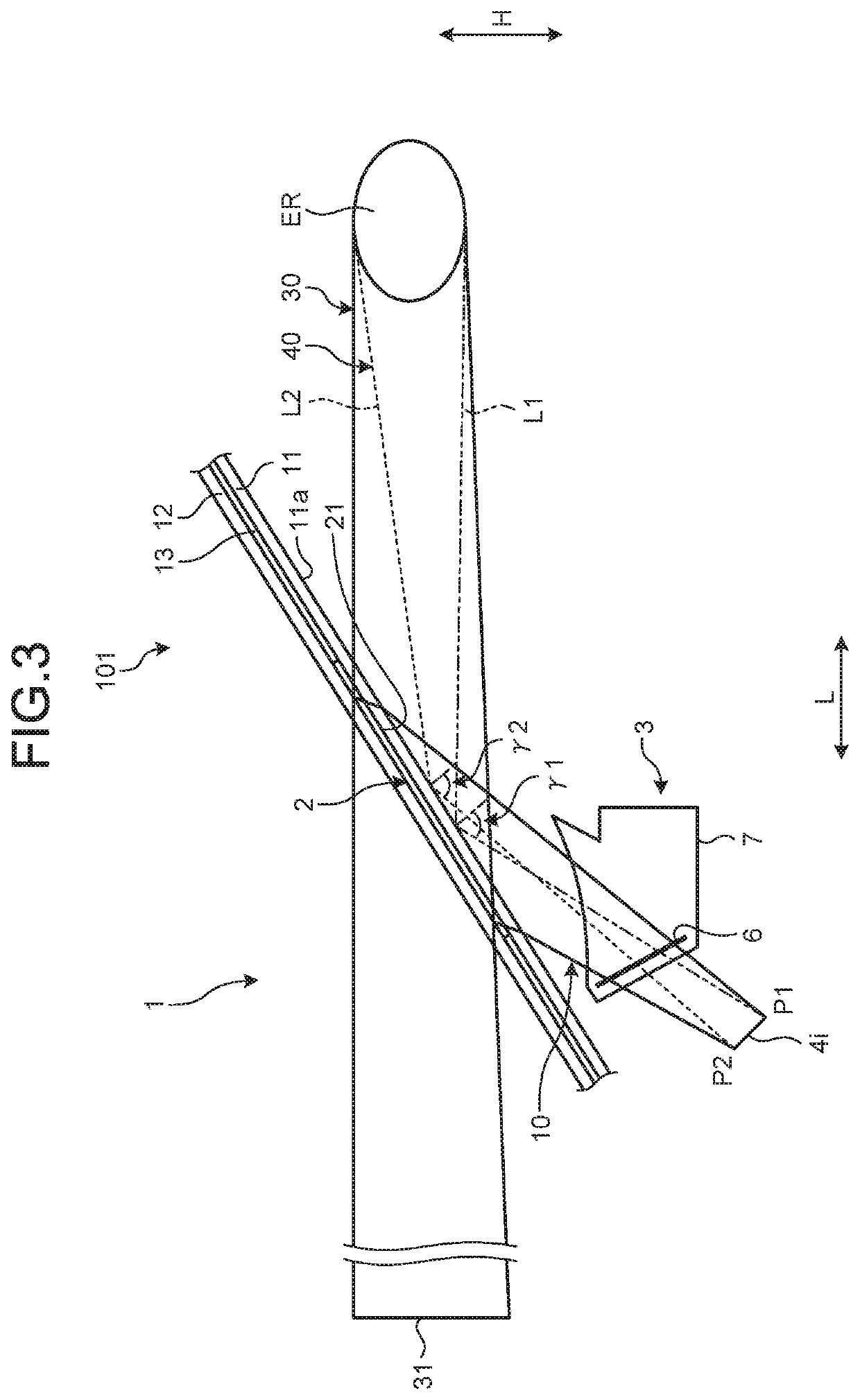
[0018]With reference to FIG. 1 to FIG. 6, the embodiment will be described. The present embodiment relates to a vehicular display device. FIG. 1 is a schematic configuration diagram of a vehicular display device according to an embodiment; FIG. 2 is a diagram explaining the diffraction of light by a hologram according to the embodiment; FIG. 3 is a diagram explaining light reflected by a windshield; FIG. 4 is a diagram explaining first reflected light and second reflected light of the embodiment; FIG. 5 is a diagram illustrating reflection characteristics in the windshield of the embodiment; and FIG. 6 is a diagram explaining a method for determining the arrangement of a projection device according to the embodiment.

[0019]As illustrated in FIG. 1, a vehicular display device 1 of the present embodiment is a head-up display device mounted on a vehicle 100 such as an automobile. The vehicular display device 1 has a hologram 2 and a projection device 3. The hologram 2 is disposed inside...

modified example of embodiment

[0048]The modified example of the embodiment will be described. The arrangement and characteristics of the hologram 2 are not limited to the arrangement and characteristics illustrated in the aforementioned embodiment. The predetermined angle range Rγ does not necessarily include the Brewster angle β. The predetermined angle range Rγ is appropriately determined such that it is possible to reduce the reflection rate Rp on the windshield 101.

[0049]The contents disclosed in the aforementioned embodiment and modified example can be combined and executed as appropriate.

[0050]In the vehicular display device according to the present embodiment, the projection device is disposed such that an angle difference between an incident angle included in a predetermined angle range and the Brewster angle is equal to or smaller than the predetermined value. In accordance with the vehicular display device according to the present embodiment, it is possible to improve the visibility of a display image ...


PUM


Abstract

A vehicular display device includes: a reflection-type hologram disposed inside a windshield of a vehicle and including a first surface facing a side of an eye range of the vehicle; and a projection device that projects display light of a P wave toward the first surface. The hologram outputs the display light, which is incident on the first surface from the projection device, as diffracted light directed to the eye range, and has diffraction characteristics of condensing the diffracted light in the eye range. The projection device is disposed such that a part of the display light is reflected toward the eye range when an incident angle of the display light on the windshield is within a predetermined angle range.

Description

CROSS-REFERENCE TO RELATED APPLICATION(S)[0001]The present application claims priority to and incorporates by reference the entire contents of Japanese Patent Application No. 2019-161913 filed in Japan on Sep. 5, 2019.BACKGROUND OF THE INVENTION1. Field of the Invention[0002]The present invention relates to a vehicular display device.2. Description of the Related Art[0003]In the related art, there is a display device using a hologram. Japanese Patent Application Laid-open No. 11-91401 discloses a vehicular holographic display device including an information display source that generates information to be displayed as light, and a combiner having a hologram that is arranged in a dark color concealing part provided on a peripheral edge part of a windshield of a vehicle, diffracts light toward an observer, and displays the light as a virtual image.[0004]When the hologram is disposed inside the windshield, it is necessary to consider the reflection of the display light by the surface of...

Claims


Application Information

Patent Timeline
Patent Type & Authority Applications(United States)
IPC IPC(8): G02B27/01B60K35/00
CPCG02B27/0103B60K35/00G02B2027/0118B60K2370/785B60K2370/29B60K2370/334B60K2370/1529G02B27/0179G02B2027/0105G02B2027/0183B60K2370/39B60K2370/66G02B27/0018
Inventor OGISU, TAKUMAAOKI, KUNIMITSU
Owner YAZAKI CORP
Why Eureka
Try Eureka