Method and device for detecting defects in the closure of encapsulated vials

a technology of encapsulated vials and defects, which is applied in the direction of packaging goods, image data processing, etc., can solve the problems of inability to manually inspect, compromise the integrity or seal of the closure, medium or large scale, etc., and achieve high reflection, high reflection, and different optical properties

Active Publication Date: 2020-01-30
GRIFOLS WORLDWIDE OPERATIONS
View PDF0 Cites 2 Cited by
  • Summary
  • Abstract
  • Description
  • Claims
  • Application Information

AI Technical Summary

Benefits of technology

[0041]Preferably, said control device also comprises a vial supply device. Advantageously, said vial supply device operates continuously. The above allows the control device to operate in an automated and uninterrupted manner, as said vial supply device is responsible for transferring the next vial to the control device once the inspection of the vial is complete. Advantageously, said vial supply device may also remove the vial from the control device after being inspected.
[0042]Preferably, said profilometer carries out the measurement of the profile using two different exposure times. Preferably, the first exposure time is between 20 μs and 100 μs and the second exposure time is between 150 μs and 500 μs. More preferably, the first exposure time is between 30 μs and 50 μs. More preferably, the second exposure time is between 250 μs and 350 μs. Owing to the use of two different exposure times a precise measurement can be taken along the entire profile of the capsule and of the vial because, since said capsule and vial are usually made of different materials, they also have different optical properties; therefore, particular reflection times are effective for measuring the capsule but produce high reflection on the vial, or vice versa. In other words, said reflection times are effective for measuring the vial but produce high reflection on the capsule. By combining the measurements obtained using both exposure times a precise reading can be obtained along the entire length of the profile of the encapsulated vial.
[0043]In one embodiment, the profilometer takes the measurement of the profile using more than two different exposure times. In said embodiment, the multiple measurements are combined in order to obtain a precise reading of the profile of the vial and of the capsule thereof. In another alternative embodiment, the profilometer takes the measurement of the profile using a single exposure time.
[0044]Preferably, the device comprises means for rotating the vial on its own longitudinal axis, thus obtaining the profile of the capsule and of the vial along the entire circumference of said capsule and vial. Advantageously, the control device is configured to correct and / or absorb small deviations between the axis of rotation of the vial and the geometric longitudinal axis thereof; in other words, the control device is configured to correct the variations that might be produced if the encapsulated vial rotates eccentrically.
[0045]Alternatively, the device comprises means for rotating the profilometer about the longitudinal axis of the vial, thus obtaining the profile of the capsule and of the vial along the entire circumference of said capsule and vial. Preferably, the control device is configured to correct and / or absorb small deviations between the axis of rotation of the profilometer and the longitudinal geometric axis of the encapsulated vial; in other words, the control device is configured to correct the variations that might be produced if the circumference described by the path of the profilometer and the vial are not concentric.
[0046]By rotating the encapsulated vial or the profilometer a three-dimensional measurement of the encapsulated vial can be obtained from two-dimensional measurements, and it is therefore possible to detect defects over the entire perimeter of the capsule of the vial. In this case, preferably, the separation between different measurement planes is small, for example, 0.5 or 1 degree of circumference. However, it is also possible to take more spaced out measurements, for example, in planes separated by 45, 90 or 120 degrees, thus checking the encapsulation at eight, four or three points respectively. It should be understood that the above examples are simply illustrative and not limiting, and it is possible to modify the separation between planes as required.

Problems solved by technology

Among the defects that may occur in the closure of vials, particularly noteworthy is the lack of seal of said closure; however, this defect is not the only one, as vials having a sealed closure may have another type of defect which, over time, may ultimately compromise the integrity or seal of the closure.
On a small scale, manual inspection of the vials by an operator is feasible, but on a medium or large scale manual inspection is not feasible owing to obvious productivity problems.
Both systems are incapable of evaluating possible defects in a capsule which encloses said cap, and the use thereof is therefore not recommended for inspecting encapsulated vials.
The inspection machine disclosed by document WO 95 / 04267 A1 only inspects the walls of the bottles, that is, said machine does not inspect the closure thereof, and consequently is not capable of detecting defects in said closure.
Although the method and the device disclosed by document WO 2016 / 202528 A1 may be used for a variety of containers and closures, said document does not disclose that said method and device can be used to inspect encapsulated vials and / or encapsulated closures, and consequently neither does it disclose what parameters should be evaluated in order to be able to detect defects in the closure of encapsulated vials.
In addition, said method and device have the drawback that measurement of an object in three dimensions by triangulation of points from two images requires a high computational load.

Method used


Image

  • Method and device for detecting defects in the closure of encapsulated vials
  • Method and device for detecting defects in the closure of encapsulated vials
  • Method and device for detecting defects in the closure of encapsulated vials

Examples


Embodiment Construction

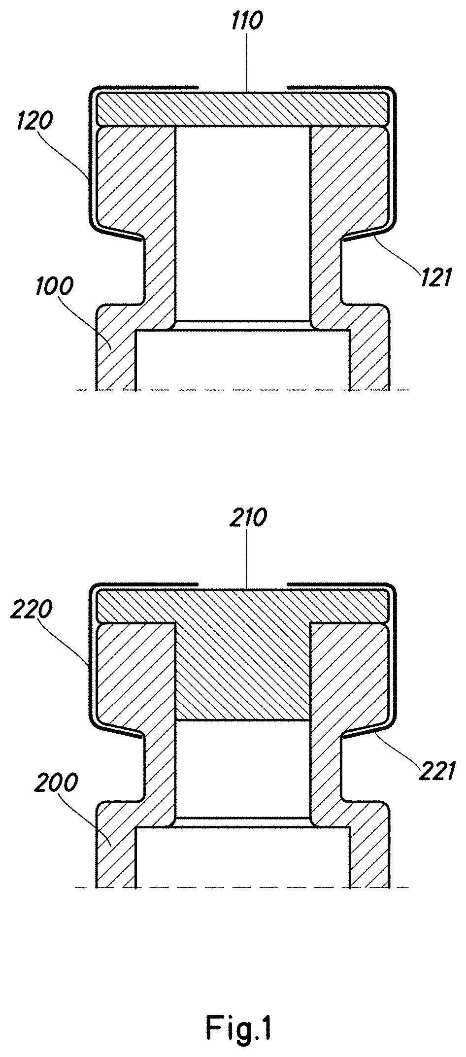
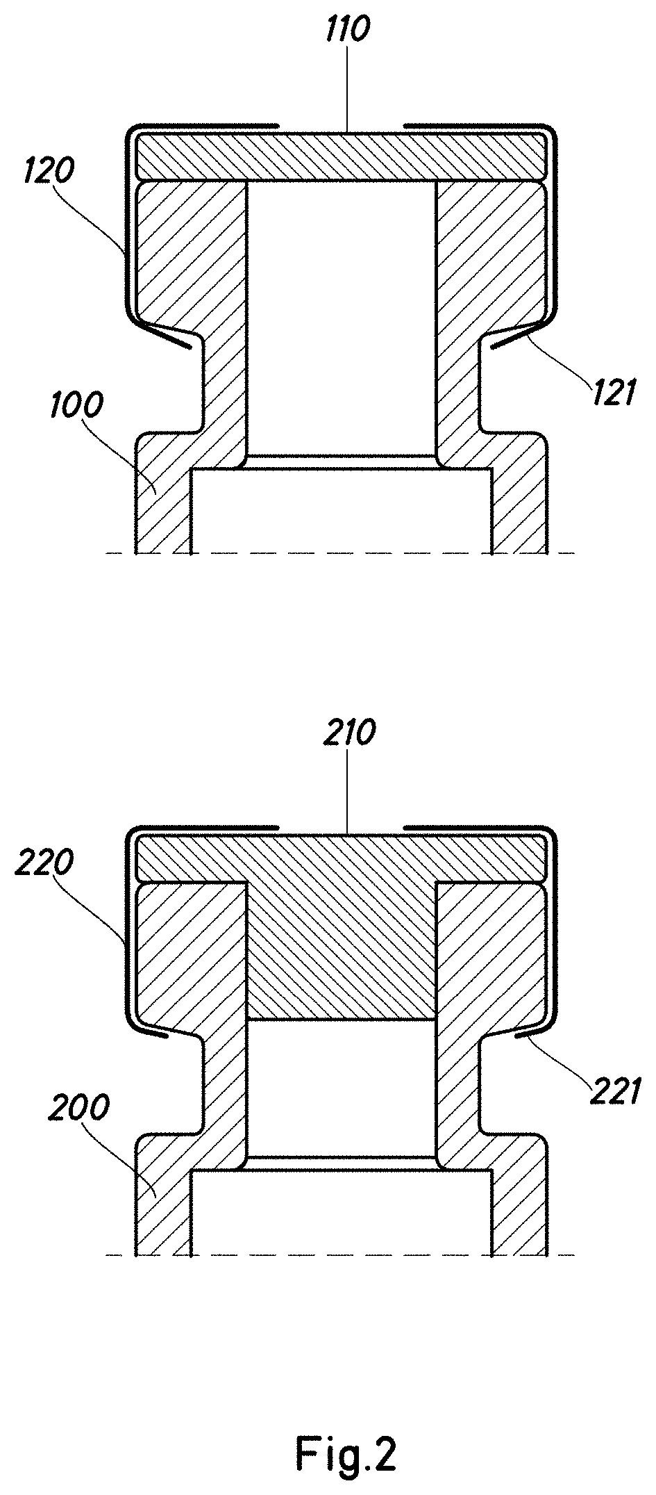
[0063]FIG. 1 shows two different vials correctly encapsulated. As can be seen, both vials -100-,-200- have a cap -110-,-210- and a capsule -120-,-220- responsible, among other things, for holding the cap -110-,-210- firmly attached to the respective vial -100-,-200- so that a sealed closure is created. The main difference between the two vials -100-,-200- arises from the fact that the vial -100- has a planar cap -110- positioned above the neck thereof, whereas the vial -200- has a cap -210- which is inserted in the neck or mouth thereof. On both vials -100-,-200- the respective capsule -120-,-220- tightly surrounds the head of the vial -100-,-200-; additionally, as well as fitting tightly on the lower portion of the head of the respective vial -100-,-200-, the lower skirt -121-,-221- of the capsules -120-,-220- has a length similar to that of the head, thus reaching as far as, or practically as far as, the neck of the vial -100-,-200-.

[0064]Although In FIG. 1 only two types of encap...


PUM

PropertyMeasurementUnit
exposure timeaaaaaaaaaa

Abstract

A method and device detect defects in the closure of encapsulated vials. The method includes scanning a profile of the capsule and of the vial using a profilometer, thus obtaining a point cloud. From the point cloud obtained, calculating at least one of the following parameters: diameter or radius of the closure circumference of the capsule; angle of intersection between the lower skirt and the side of the capsule; length of the lower skirt; and/or a distance from the end of the lower skirt to the neck of the vial. The method determines whether any of the parameters calculated in the previous step exceeds a predetermined value. The device detecting defects in the closure of encapsulated vials includes a profilometer configured to scan a profile of the capsule and of the vial and a control device configured to execute the method.

Description

[0001]This application claims benefit of European Patent Application No. 18382571.0, filed 30 Jul. 2018 and which application is incorporated herein by reference. To the extent appropriate, a claim of priority is made to the above-disclosed application.BACKGROUND OF THE INVENTION[0002]The present invention relates to a novel method and device for detecting defects in the closure of vials. More specifically, the present invention discloses a novel method and device for detecting defects in the closure of encapsulated vials.[0003]These days, especially in the pharmaceutical industry, the use of vials is widespread. The vials are generally small receptacles which can be used to contain medicines, samples, etc. in the form of liquids, powders or capsules. The vials may have different types of closure, such as encapsulated caps, screw-on caps, flip-up caps, rubber caps or similar, etc.[0004]To prevent losses and / or contamination of the contents of the vial, it is very important to ensure...

Claims


Application Information

Patent Timeline
Patent Type & Authority Applications(United States)
IPC IPC(8): G01N21/90G01N21/88G01N21/95G01B11/25G01B11/08
CPCG01N21/8851G01N2021/8887G01N21/9508A61J1/1412G01N21/9054G01N2201/10G01B11/08G01B11/2518G01N21/88G01N21/01G01B11/24G01N2021/0112G01B11/00G01N21/9027G01N21/909G01N2201/103G06T7/0002G01N2201/106G01N2201/06113B67B3/264
Inventor BOIRA BONHORA, JORDIROURA SALIETTI, CARLOSCOCA GARROTE, JOSE
Owner GRIFOLS WORLDWIDE OPERATIONS
Why Eureka
Try Eureka