Eureka AIR delivers breakthrough ideas for toughest innovation challenges, trusted by R&D personnel around the world.

Method of stabilizing laser beam, and laser beam generation system

a laser beam and laser beam technology, applied in the direction of laser details, active medium materials, electrical devices, etc., can solve the problems of unfavorable laser beam stabilization, so as to maintain the characteristic in a good condition for a long time, enhance reliability, and maintain constant characteristics

Inactive Publication Date: 2005-01-27
SONY CORP
View PDF22 Cites 32 Cited by
  • Summary
  • Abstract
  • Description
  • Claims
  • Application Information

AI Technical Summary

Benefits of technology

[0046] The present invention has been made in order to solve the above-mentioned problems. Accordingly, it is an object of the present invention to provide a method of stabilizing a laser beam and a laser beam generation system with which it is possible to vary the resonator length, to compensate for variations in a characteristic of a laser beam, and to obtain long-term stability.
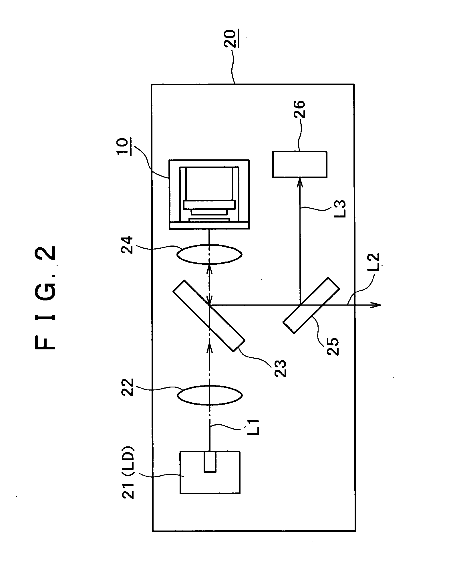
[0047] In accordance with one aspect of the present invention, there is provided a method of stabilizing a laser beam generated from a laser beam generation system including a solid state laser oscillator excited by an excitation beam, and a Q switch for pulsating laser oscillation by use of a saturable absorber, wherein the laser beam generation system is so configured that the optical path length of a laser resonator can be varied, a pulse of the generated laser beam is detected, and the variation of the optical path length of the laser resonator is controlled based on a characteristic of the detected pulse.

Problems solved by technology

However, the Q switch laser using a saturable absorber has the drawback that the repetition frequency would be varied to an undesired value due to a change in characteristics peculiar to the saturable absorber (for example, a change in saturable absorption quantity), a change in characteristics of the laser resonator (for example, a change in gain or loss), or the like.
In addition, such a variation may be attended by a variation in pulse peak output power and may cause a variation in average oscillation power.
The variation in pulse repetition frequency, the variation in pulse peak output, and the variation in average power have been obstacles in application of the Q switch laser.
For practical use, however, the configuration has two problems: one relates to the formation of a stable laser resonator, and the other to the selection of the operating point.
On the other hand, if the optical path in the resonator is not perpendicular to the mirrors at both ends, the resonator loss would increase, to cause such problems as a lowering in output, defective pulse operations, and generation of transverse mode, resulting in that a stable resonator cannot be formed.
In order to form a stable resonator, therefore, the optical component parts of the resonator must have an extremely high parallelism, which increases the production and assembly costs.
The problem relating to the selection of the operating point is that when the optical component parts of the resonator are fixed, the operating point cannot be selected, and, on the other hand, if the optical component parts are not fixed, the operating point would not be constant.
The Q switch laser including a saturable absorber, if not oscillated in longitudinal single mode, would show such an oscillation that a plurality of pulses differing in pulse period or timing are superposed, which is unfavorable for the normal operation expected to generate a pulse train with a fixed timing.
However, it is not possible to match the oscillation frequency to the gain peak, as originally desired.
Particularly, in the case where the gain peak is located substantially at the midpoint between two adjacent longitudinal modes, the two longitudinal modes concur, leading to instability of the pulse, and, for a shifting from such an operating point to the desired operating point, resonator length regulation means for regulation by not less than about ¼ times the wavelength is needed.
In conclusion, the conventional configuration as shown in FIG. 12 can cope with the problems as to the accuracy of component parts or in assembly and the steadiness after adhesion, but cannot permit modification of the resonator length.
Therefore, the conventional configuration has the problem that it is difficult to set the initial operating point at a favorable position.
In addition, where this configuration of the Q switch laser 110 is adopted, changes with time are generated, whereby long-term stability is lost.
As a result, even at the same resonator temperature, the operating point may be changed toward the worse side from the designed operating point.
Such a change causes variations in the temperatures giving maximal values of average power and repetition frequency and in the maximal values (peak heights), resulting in that the original characteristics cannot be recovered by simply recovering the original temperature.
In the case of a system utilizing repetition frequency, the variation in the repetition frequency constitutes a problem.
On the other hand, in the case where pulse peak power is utilized, the variation in the peak power has adverse effects on the micro-process and the like.
Further, in the case of using such a laser as a master laser for an amplifier such as a fiber laser, a semiconductor laser, and a solid state laser to thereby construct a so-called MOPA (Master Oscillator Power Amplifier), there may occur the problems that the variation in repetition frequency causes variations in energy amplification value of each pulse, that the variation in peak power damages the amplifier or optical systems used in the subsequent stages, and that nonlinear optical effects such as inductive Raman scattering and self phase modulation cause a lowering in efficiency in the form an energy shift to an unexpected wavelength or deformation of the pulse shape.

Method used


Image

  • Method of stabilizing laser beam, and laser beam generation system
  • Method of stabilizing laser beam, and laser beam generation system
  • Method of stabilizing laser beam, and laser beam generation system

Examples


Embodiment Construction

[0072] Now, as embodiments of the present invention, one embodiment of the laser beam generation system and the method of stabilizing a laser beam in the laser generation system will be described.

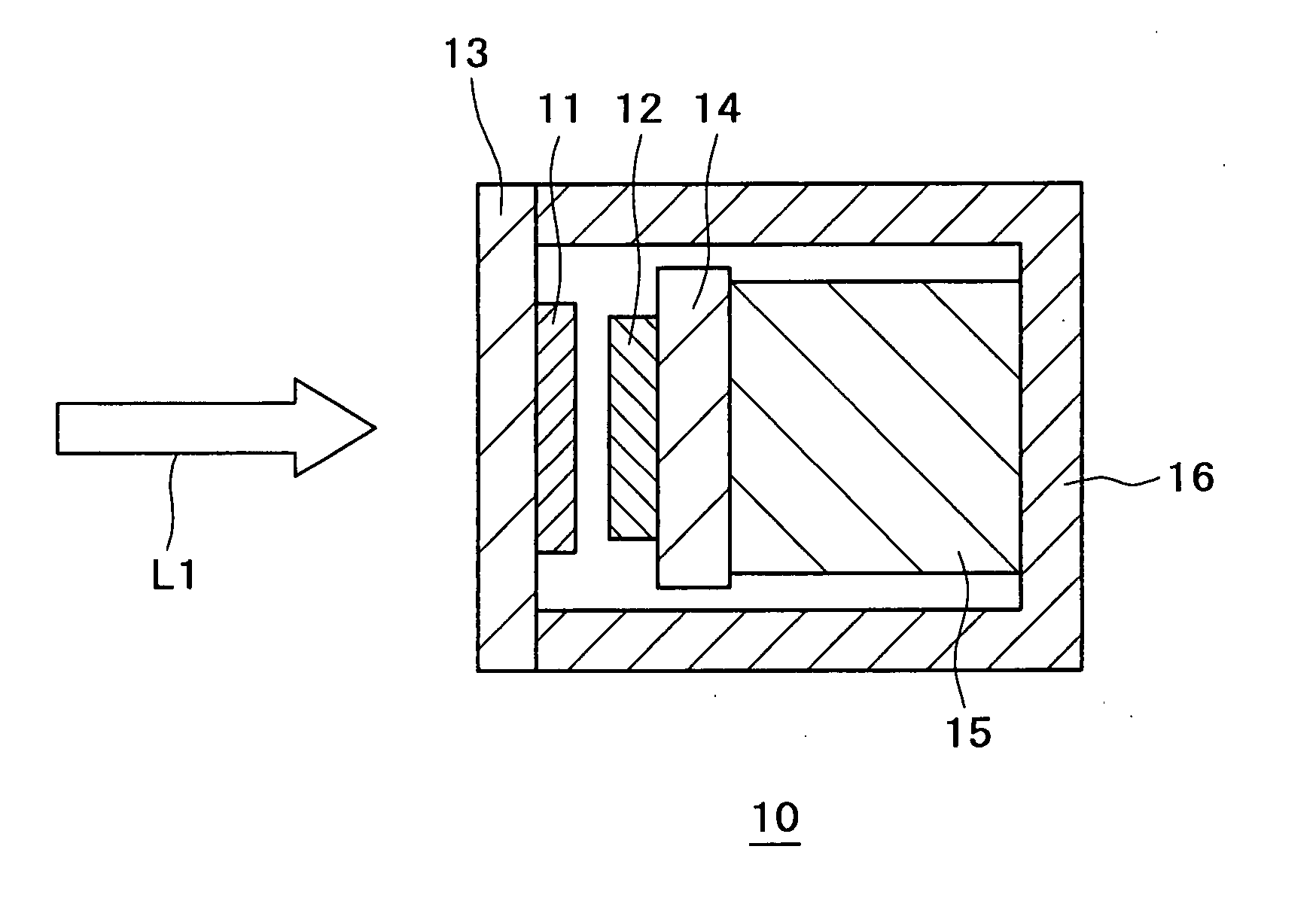
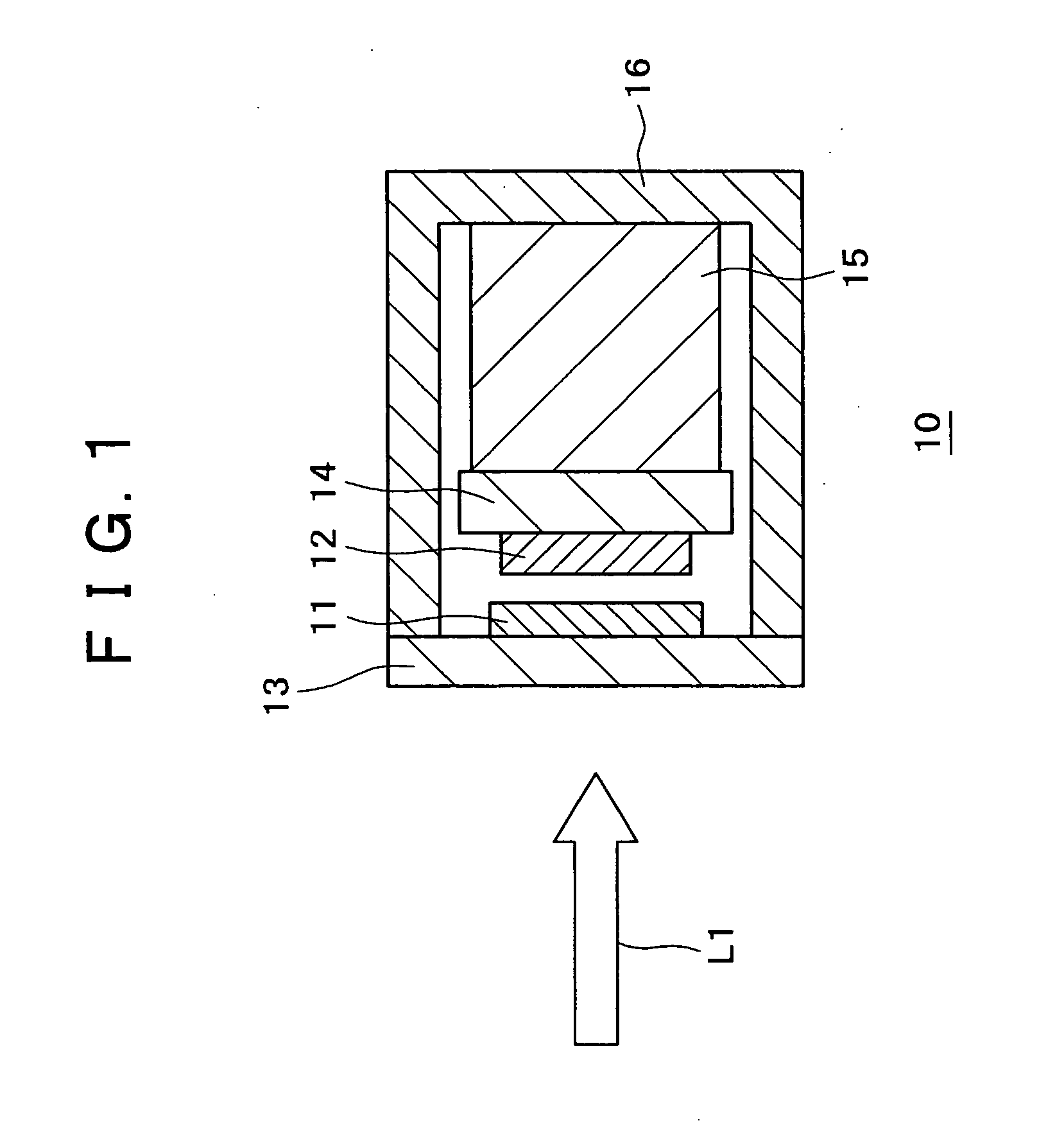
[0073] First, FIG. 1 schematically illustrates the configuration of a laser oscillator constituting the laser beam generation system according to this embodiment.

[0074] The laser oscillator 10 has a structure in which a laser medium 11 and an SBR (Saturable Bragg Reflector) 12 are disposed opposite to each other and are attached respectively to support members 13 and 14 which are formed of quartz, sapphire or the like.

[0075] As the laser medium 11, for example, Nd:YVO4, Nd:YLF (YliF4) and the like can be used. The oscillation wavelengths of Nd:YVO4 are 1064 nm and 1340 nm, while the oscillation wavelength of Nd:YLF is 914 nm.

[0076] Other than these, optical crystals or glasses doped with a rare earth element such as Nd, Er, Yb, Sm, and Pr can also be used.

[0077] As has been mentioned a...


PUM


Abstract

A laser beam generation system comprises a solid state laser oscillator excited by an excitation beam, and a Q switch for pulsating laser oscillation by use of a saturable absorber, wherein the optical path length of a laser resonator is variable. The pulse of a laser beam generated from the laser beam generation system is detected, and variation of the optical path length of the laser resonator is controlled based on a characteristic of the detected pulse, to thereby stabilize the laser beam. The laser beam generation system may further comprise resonator length regulation element for varying the optical path length of the laser resonator, and detection element for detecting the pulse laser beam outputted, wherein the optical path length of the laser resonator is regulated by the resonator length regulation element based on a characteristic of the pulse detected by the detection element.

Description

BACKGROUND OF THE INVENTION [0001] The present invention relates to a method of stabilizing a laser beam and a laser beam generation system, and particularly to a Q switch laser. [0002] A Q switch laser using a saturable absorber is promising as a technology for realizing a Q switch laser by using a continuous oscillation type excitation light source but not using a modulator such as an AOM (Acousto Optical Modulator) or an RF oscillator, and is promising as means for easily realizing a small-type Q switch laser or a high-repetition Q switch laser. [0003] A typical configuration of the Q switch laser using a saturable absorber is shown in FIG. 12 (see Spuhler et al., J. Opt. Soc. Am., Vol. 16, No. 3 (1999), pp.376-388) (this reference will hereinafter be referred to as Non-patent Reference 1). [0004] In this exemplary configuration, a passive Q switch laser is excited by a semiconductor laser. [0005] The Q switch laser 100 shown in FIG. 12 includes a laser medium 101 using Nd:YVO4, ...

Claims


Application Information

Patent Timeline
IPC IPC(8): H01S3/137H01S3/094H01S3/098H01S3/1055H01S3/13H01S3/16
CPCH01S3/10046H01S3/1055H01S3/1118H01S3/1673H01S3/1611H01S3/1653H01S3/1305
Inventor MORITA, MASAYUKIHAYASHIBE, KAZUYAAKIYAMA, YOSHIYUKIMASUDA, HISASHI
Owner SONY CORP
Why Eureka
Eureka Blog
Learn More