Antenna

a technology of ring resonator and antenna, which is applied in the direction of antenna equipment with additional functions, antenna details, antennas, etc., can solve the problems that an antenna with four or more fixed portions cannot have constant or stable characteristics, and achieve the effect of constant characteristics

Active Publication Date: 2022-08-16
JAPAN AVIATION ELECTRONICS IND LTD
View PDF18 Cites 0 Cited by
  • Summary
  • Abstract
  • Description
  • Claims
  • Application Information

AI Technical Summary

Benefits of technology

[0007]The antenna of the present invention is fixed on a circuit board by the three fixed portions, or the first fixed portion, the second fixed portion and the third fixed portion. The three fixed portions can prevent variation of attitude of the antenna upon mounting of the antenna on a circuit board. Thus, the antenna of the present invention can have constant characteristics.

Problems solved by technology

Thus, the antenna with four or more of the fixed portions cannot have constant or stable characteristics.

Method used


Image

  • Antenna
  • Antenna
  • Antenna

Examples


Embodiment Construction

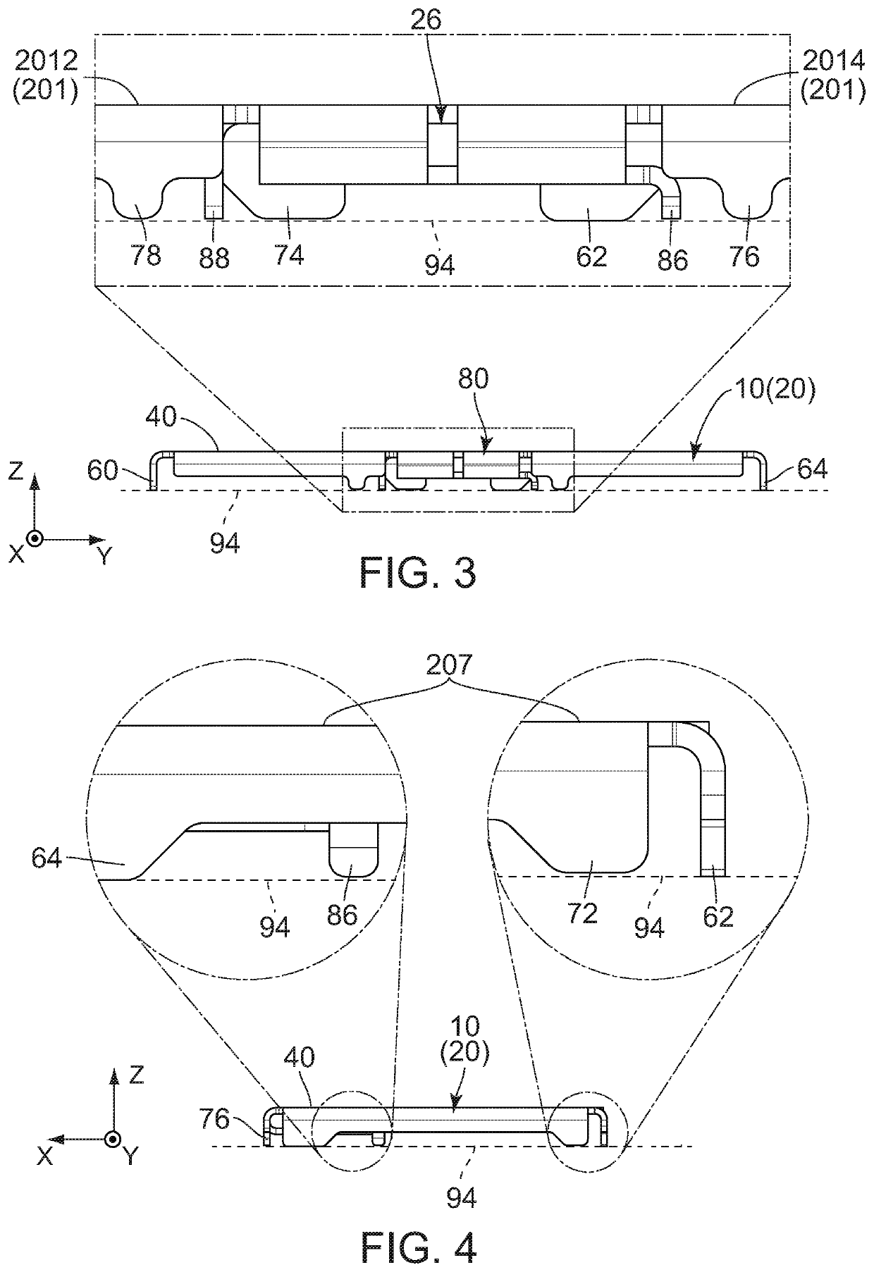
[0020]Referring to FIG. 3, an antenna 10 according to an embodiment of the present invention is a discrete member which is mounted on a circuit board (not shown) when used. The circuit board has an upper surface (not shown), and the upper surface is formed with a plurality of connecting pads (not shown). In addition, the circuit board comprises a feed line (not shown) and a ground plane (not shown).

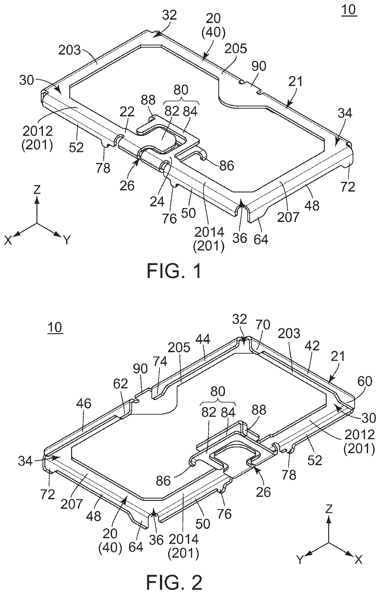
[0021]Referring to FIG. 1, the antenna 10 of the present embodiment is the discrete member which is formed by punching out a single metal plate, followed by bending it. The antenna 10 has a split ring resonator. In other words, the antenna 10 of the present embodiment is a resonant antenna. The antenna 10 comprises a main portion 20 and a facing portion 80.

[0022]Referring to FIG. 1, the main portion 20 of the present embodiment forms a split ring 21. In other words, the antenna 10 comprises the main portion 20 which forms the split ring 21. The main portion 20 has an angular C-shape. Spec...


PUM


Abstract

An antenna comprises a split ring resonator. The antenna has a main portion which forms a split ring with a split portion. The main portion has an upper surface portion, a first fixed portion, a second fixed portion, a third fixed portion, a first reinforcing portion, a second reinforcing portion, a feed portion, a first end portion and a second end portion. Each of the first fixed portion, the second fixed portion and the third fixed portion is fixed on a circuit board when the antenna is mounted on the circuit board. Lower ends of the first fixed portion, the second fixed portion and the third fixed portion define an imaginary plane perpendicular to an up-down direction. Each of lower ends of the first reinforcing portion, the second reinforcing portion and the feed portion is positioned between the upper surface portion and the imaginary plane in the up-down direction.

Description

CROSS REFERENCE TO RELATED APPLICATIONS[0001]This application is based on and claims priority under 35 U.S.C. § 119 to Japanese Patent Application No. JP2019-220300 filed Dec. 5, 2019, the contents of which are incorporated herein in their entirety by reference.BACKGROUND OF THE INVENTION[0002]This invention relates to an antenna comprising a split ring resonator.[0003]Referring to FIGS. 8 and 9, an antenna 900 of JPS1633799 comprises a split ring resonator. Specifically, the antenna 900 comprises a main portion 910 and a facing portion 920. The main portion 910 mainly functions as an inductor, and the facing portion 920 mainly functions as a capacitor. The main portion 910 forms a split ring. The main portion 910 is provided with a feed terminal 912. The facing portion 920 is provided on a split portion of the split ring. The main portion 910 is soldered on a circuit board by three fixed portions 930 at three points. The three fixed portions 930 prevent variation of attitude of the...

Claims


Application Information

Patent Timeline
Patent Type & Authority Patents(United States)
IPC IPC(8): H01Q7/00H01Q1/38
CPCH01Q7/00H01Q1/38H01Q1/22H01Q1/50H01Q1/36H01Q1/12H01Q1/1207H01Q1/46
Inventor HASHIGUCHI, OSAMU
Owner JAPAN AVIATION ELECTRONICS IND LTD
Why Eureka
Try Eureka