

Antenna
- Summary
- Abstract
- Description
- Claims
- Application Information
AI Technical Summary
Benefits of technology
Problems solved by technology
Method used
Image

Examples
Embodiment Construction
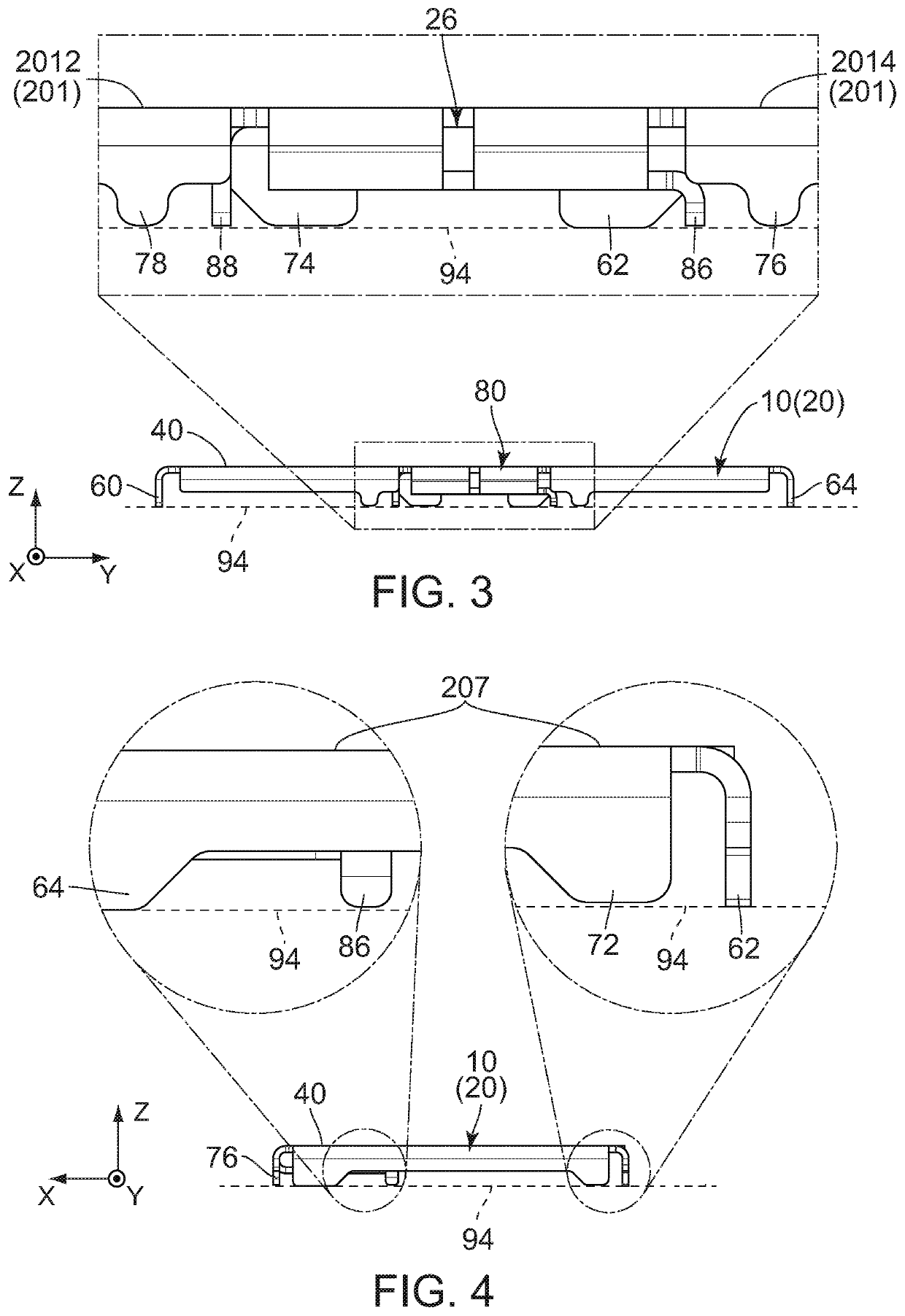
[0020]Referring to FIG. 3, an antenna 10 according to an embodiment of the present invention is a discrete member which is mounted on a circuit board (not shown) when used. The circuit board has an upper surface (not shown), and the upper surface is formed with a plurality of connecting pads (not shown). In addition, the circuit board comprises a feed line (not shown) and a ground plane (not shown).
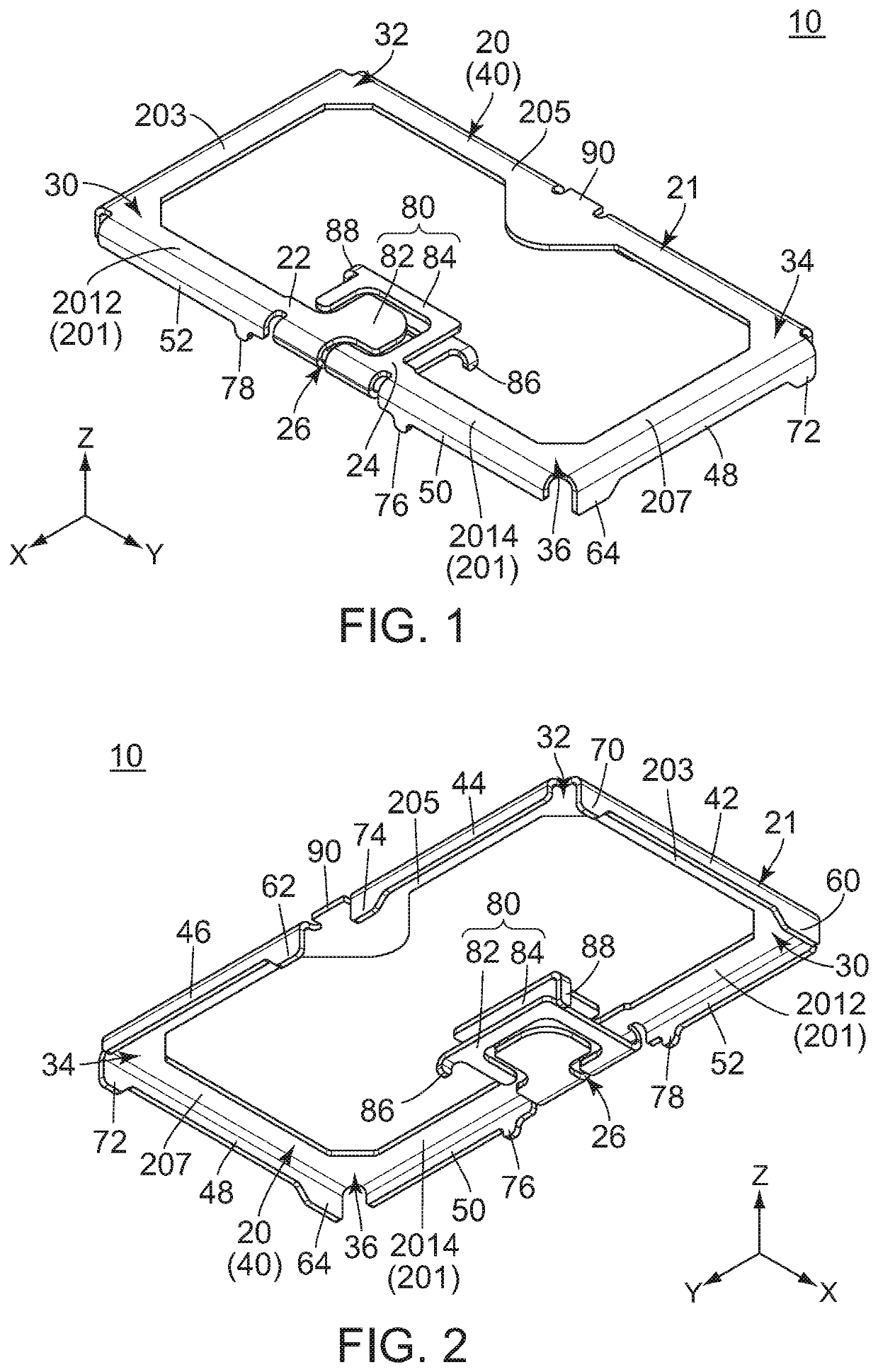
[0021]Referring to FIG. 1, the antenna 10 of the present embodiment is the discrete member which is formed by punching out a single metal plate, followed by bending it. The antenna 10 has a split ring resonator. In other words, the antenna 10 of the present embodiment is a resonant antenna. The antenna 10 comprises a main portion 20 and a facing portion 80.
[0022]Referring to FIG. 1, the main portion 20 of the present embodiment forms a split ring 21. In other words, the antenna 10 comprises the main portion 20 which forms the split ring 21. The main portion 20 has an angular C-shape. Spec...
PUM
 Abstract
Description
Claims
Application Information