Spray lance arrangement

a technology of spray lance and nozzle, which is applied in the direction of rotary stirring mixer, transportation and packaging, and separation processes, etc., can solve the problems of less efficient mixing of water and dust in the mixer, less efficient removal of gaseous pollutants from process gases, etc., and achieve the effect of reducing the spray load

Active Publication Date: 2016-10-04
ANDRITZ AB
View PDF9 Cites 0 Cited by
  • Summary
  • Abstract
  • Description
  • Claims
  • Application Information

AI Technical Summary

Benefits of technology

[0007]An advantage of this two media spray lance and nozzle is that by adjusting the volume of air flow from the plurality of second openings into the liquid flow within the liquid supply pipe, the spraying characteristics of the nozzle, such as the spray angle, are very constant. Such is the case even when the pressure of the liquid supplied to the nozzle is varied for purposes of matching mixer moisture demands, particularly under conditions where liquid pressures measure 2 bar or less. This makes it possible to vary the amount of liquid that is atomized by the nozzle over an especially wide range, with relatively small variations in the spray characteristics of the nozzle.
[0009]An advantage of the mixer being provided with such a two media spray lance and nozzle combination is that the moistening of the absorbent material will be efficient, with little or no water being unintentionally sprayed onto internal structures of the mixer which may lead to material clumping. Furthermore, changes in the amount of water required for moistening the dust can be handled by inversely varying the water pressures and air pressures supplied to the nozzle, so that variations in water pressures to match mixer liquid demands do not substantially influence the spray angle or the spray pattern of the nozzle. Hence, the two media spray lance allows for significantly greater water pressure variation without influencing the spray angle or spray pattern of the nozzle, by allowing for increased air pressures as water pressures are decreased.

Problems solved by technology

It has now been found that the mixing of water and dust in the mixer is sometimes less efficient, which results in less efficient removal of gaseous pollutants from the process gases.

Method used


Image

  • Spray lance arrangement
  • Spray lance arrangement
  • Spray lance arrangement

Examples


example

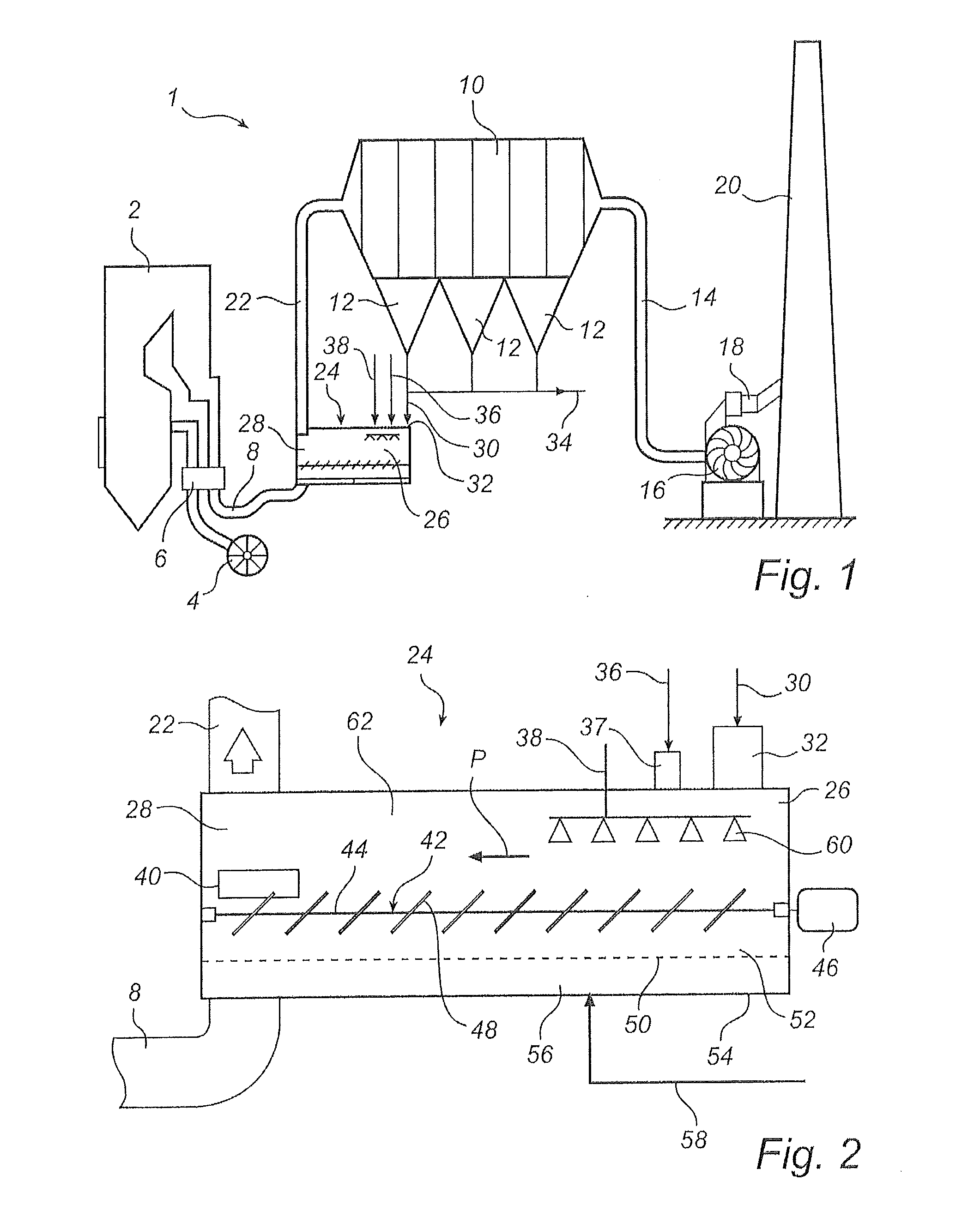
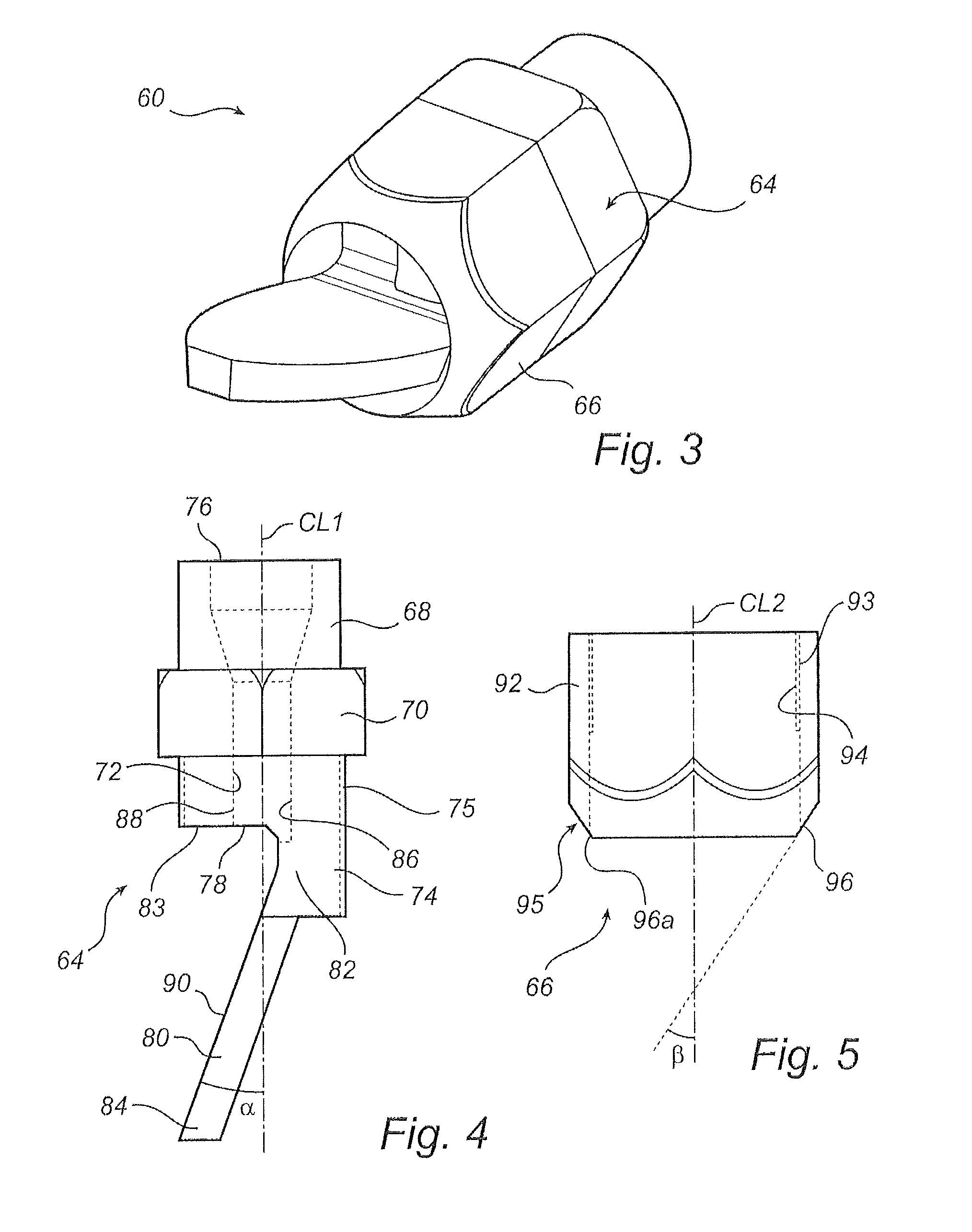
[0046]A test was performed to evaluate the influence of the water pressure on the spray angle. In particular when spraying in confined areas, such as in the mixer 24 illustrated in FIG. 2, it is important that the spray angle does not change significantly when varying the amount of water sprayed per unit of time. Varying the amount of water sprayed per unit of time is made by varying the water pressure. In the example, the nozzle 60 described hereinabove with reference to FIGS. 3-7 was compared to a nozzle of the type Spraying Systems Flatjet 5040 which is available from Spraying Systems Co. Wheaton, Ill., USA. Different water pressures (in bar overpressure, i.e. pressure above atmospheric), were supplied to the nozzles, and the spray angles, similar to angle SAW illustrated in FIG. 6b, were measured. The results are presented in Table 1, below.

[0047]

TABLE 1Spray angles of nozzles at various pressures.Spraying SystemsNozzle (60) of presentWater pressureFlatjet 5040disclosure[bar ove...


PUM

PropertyMeasurementUnit
Raaaaaaaaaaa
angleaaaaaaaaaa
angleaaaaaaaaaa

Abstract

A two media spray lance and nozzle useful for moistening at least a portion of absorbent material present in a mixer. The nozzle includes a central body with a connecting portion for connecting the nozzle to the two media spray lance for a supply of liquid and gas thereto, and an atomizing portion. The atomizing portion delivers droplets of liquid to the absorbent material present in the mixer to obtain moistened absorbent material.

Description

CROSS-REFERENCE TO RELATED APPLICATION[0001]This application claims the benefit of U.S. Provisional Patent Application Ser. No. 61 / 671,266; filed on Jul. 13, 2012, entitled “SPRAY LANCE ARRANGEMENT” which is incorporated herein by reference in its entirety.FIELD OF THE INVENTION[0002]The present disclosure relates to a two media spray lance and nozzle combination for spraying a liquid. Such a two media spray lance and nozzle combination may, for example, be arranged inside a mixer for moistening an absorbent material for removing gaseous pollutants from hot process gases.BACKGROUND ART[0003]When separating gaseous pollutants from process gases, such as flue gases from a coal-fired or oil-fired power plant, a method is frequently used in which a lime-containing absorbent material is introduced into the process gases to react with the gaseous pollutants so as to allow removal thereof. When the absorbent material reacts with the gaseous pollutants, the gaseous pollutants are converted ...

Claims


Application Information

Patent Timeline
Patent Type & Authority Patents(United States)
IPC IPC(8): B01F3/04B01F7/02B05B7/04B01F5/04B01F3/12B05B1/26B05B1/04
CPCB05B7/0491B01F3/04099B01F3/1207B01F3/1228B01F5/0403B01F5/0405B01F5/0463B01F7/022B05B1/04B05B1/267B05B7/0416B05B7/0433B01F23/54B01F25/31331B01F27/62B01F25/72B01F23/23B01F23/51B01F23/211B01F23/21321B01F23/21322B01F25/31B01F25/311B01F35/13B01F35/512B01F35/7179B01F2101/48B01D53/185B01D2252/103
Inventor LANDMER, PER HAKAN FREDRIK
Owner ANDRITZ AB
Why Eureka
Try Eureka