Vehicle curtain airbag device
a curtain airbag and vehicle curtain technology, applied in the direction of vehicular safety arrangments, vehicle components, pedestrian/occupant safety arrangements, etc., can solve the problem of difficult to achieve occupant protection in the event, and achieve the effect of effective reaction force, simple manufacture and easy manufactur
- Summary
- Abstract
- Description
- Claims
- Application Information
AI Technical Summary
Benefits of technology
Problems solved by technology
Method used
Image
Examples
first exemplary embodiment
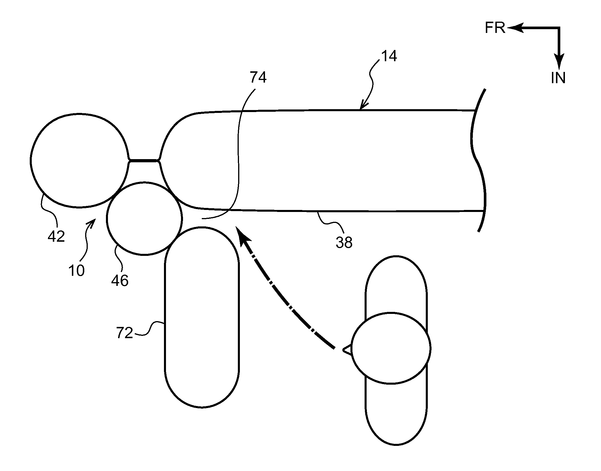
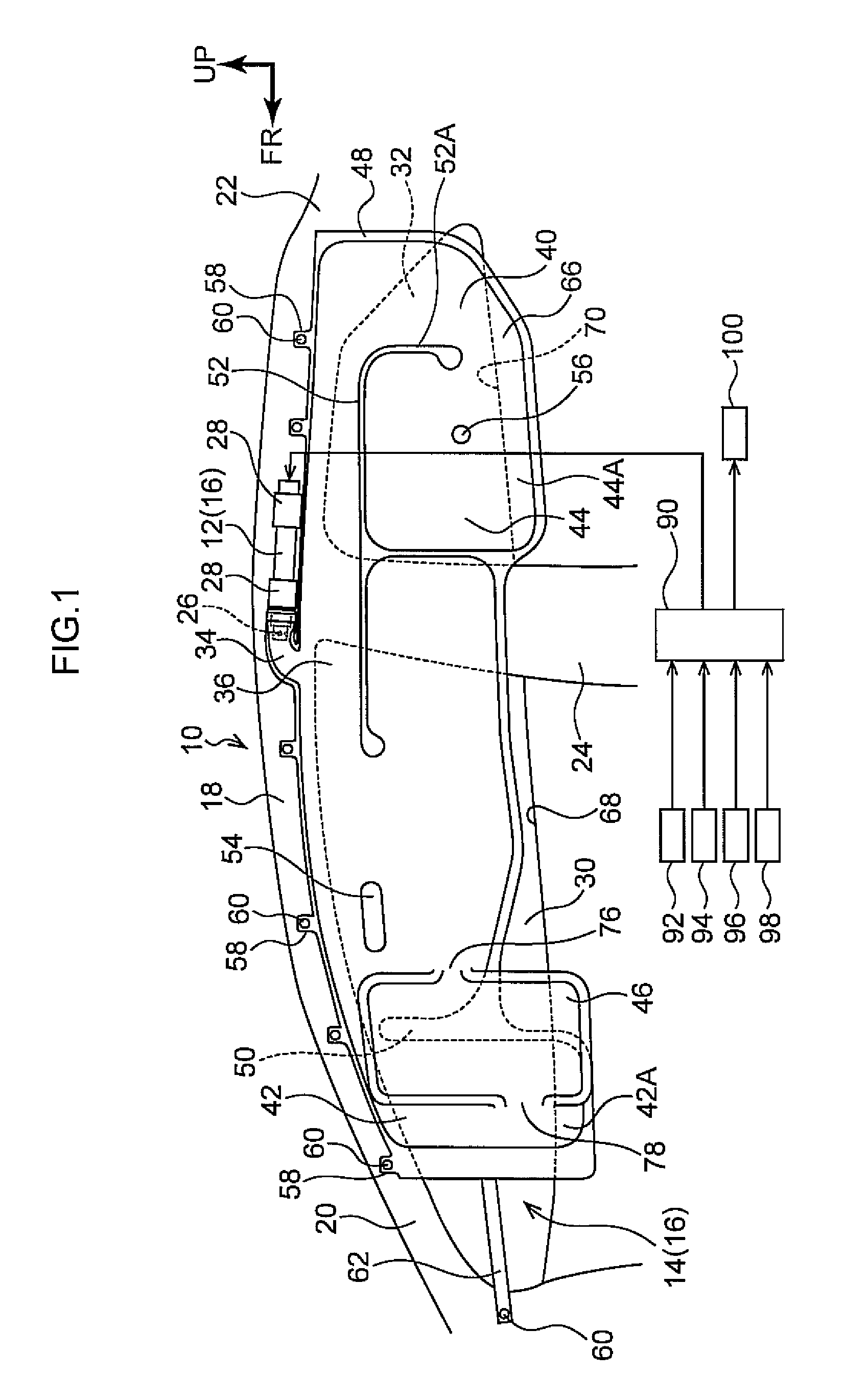
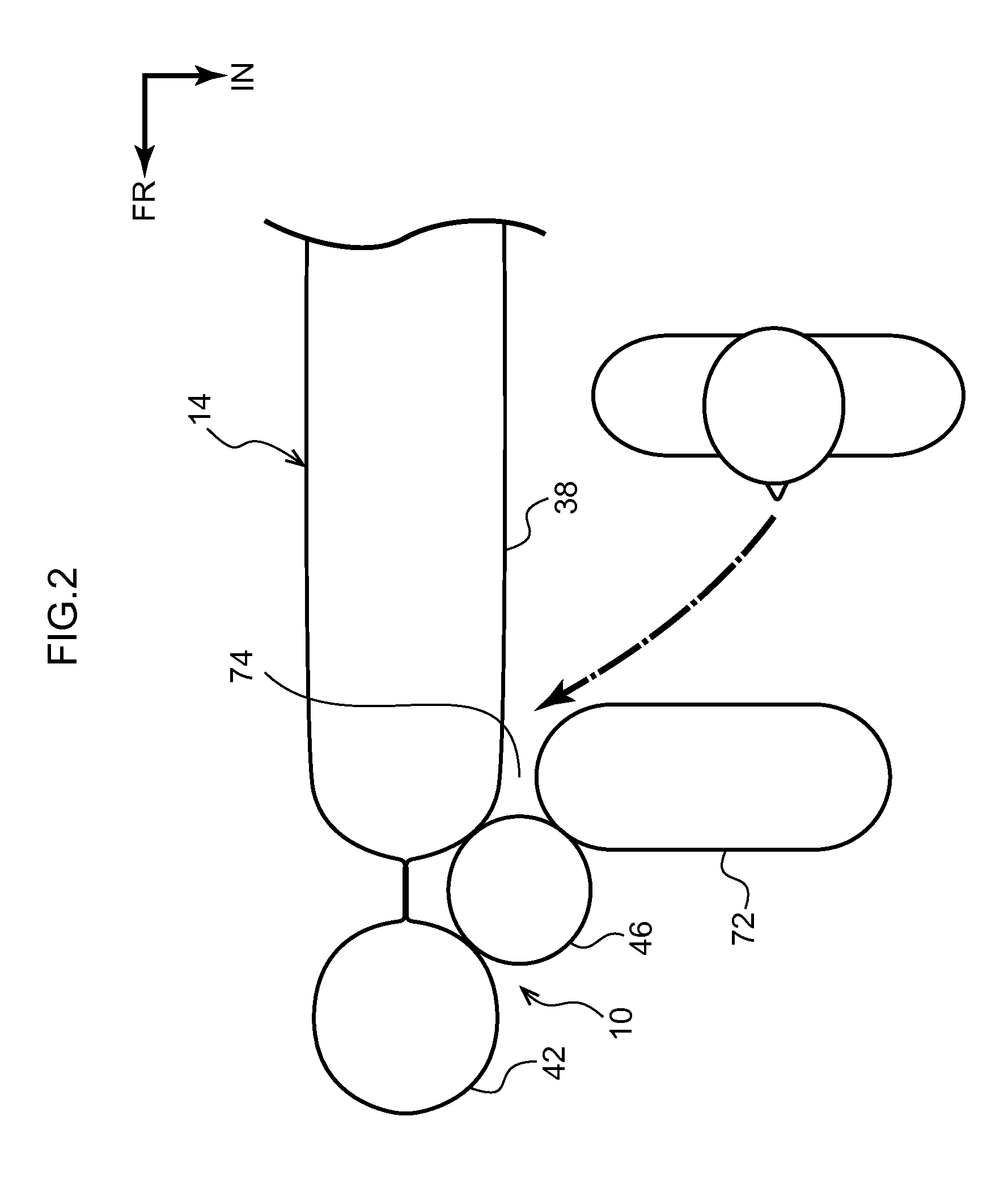
[0038]Explanation follows regarding a vehicle curtain airbag device of a first exemplary embodiment of the present invention with reference to FIG. 1 to FIG. 3. Note that in the drawings, the arrow FR indicates the vehicle front side, the arrow UP indicates the vehicle top side, and the arrow IN indicates the vehicle width direction inside as appropriate.
[0039]FIG. 1 is a side view as viewed from inside a vehicle compartment illustrating an actuated state of a vehicle curtain airbag device 10 according to the present exemplary embodiment. As illustrated in FIG. 1, the vehicle curtain airbag device 10 is equipped with an airbag module 16 configured including an inflator 12 that generates gas in the event of a side-on collision, and a curtain airbag 14 that is connected to the inflator 12 and that inflates and deploys on receipt of gas supplied from the inflator 12.
[0040]In a state prior to installation to a vehicle, the airbag module 16 is assembled with the curtain airbag 14 folded ...
second exemplary embodiment
[0065]Explanation follows regarding a vehicle curtain airbag device according to a second exemplary embodiment of the present invention, with reference to FIG. 4.
[0066]As illustrated in FIG. 4, in the second exemplary embodiment a curtain airbag 116 includes a sub chamber 110, a front main chamber 112, a front delay chamber 114, and also a rear main chamber and a rear delay chamber, neither of which are illustrated in the drawings. The overall curtain airbag 116 is integrally pocket woven using what is known as a one-piece woven (OPW) method. The OPW curtain airbag 116 is a pocket shaped non-stitched bag manufactured by weaving two pieces of cloth at the same time with connecting weaving at the required locations, on a Jacquard loom.
[0067]The vicinities of a front end portion of the front main chamber 112 and a rear end portion of the front delay chamber 114 are coupled together in the vehicle front-rear direction by a strap 118 at the vehicle width direction outside of the sub cham...
third exemplary embodiment
[0069]Explanation follows regarding a vehicle curtain airbag device according to a third exemplary embodiment of the present invention, with reference to FIG. 5A and FIG. 5B. Note that configuration portions similar to those of the first exemplary embodiment described above are allocated the same reference numerals and further explanation thereof is omitted.
[0070]As illustrated in FIG. 5A and FIG. 5B, in the third exemplary embodiment the sub chamber 46 is formed so as to be folded and bent over. More specifically, when opened out flat as a single body, a curtain airbag 120 is formed with a substantially rectangular non-inflating portion 122 at the vehicle front-rear direction front side of the front main chamber 38, and the front delay chamber 42 is further formed to the vehicle front-rear direction front side of the non-inflating portion 122. The sub chamber 46 is moreover integrally formed to the vehicle up-down direction lower side of the non-inflating portion 122. Namely, the s...
PUM
 Abstract
Description
Claims
Application Information
 - R&D
- Intellectual Property
- Life Sciences
- Materials
- Tech Scout
- Unparalleled Data Quality
- Higher Quality Content
- 60% Fewer Hallucinations
Browse by: Latest US Patents, China's latest patents, Technical Efficacy Thesaurus, Application Domain, Technology Topic, Popular Technical Reports.
© 2025 PatSnap. All rights reserved.Legal|Privacy policy|Modern Slavery Act Transparency Statement|Sitemap|About US| Contact US: help@patsnap.com


