
Method and apparatus for attachment in a modular hip replacement or fracture fixation device

a modular, hip replacement technology, applied in the field of medical methods and equipment, can solve the problems of affecting the quality of hip replacement, the failure of conventional hip replacement implants, and the release of debris or corrosion from implants, so as to improve the quality, reliability, and compatibility of implantation systems.

Inactive Publication Date: 2015-03-10
IHIP SURGICAL LLC
View PDF673 Cites 7 Cited by
  • Summary
  • Abstract
  • Description
  • Claims
  • Application Information

AI Technical Summary

Benefits of technology

[0006]In accordance with some embodiments disclosed herein, various systems, components, and methods of use and surgery are provided to enhance the quality, reliability, and compatibility of implantation systems. These apparatuses and methods can be utilized for various types of implantation systems and methods of surgery, site and system preparation, and implantation. For example, embodiments of apparatuses disclosed herein for joint replacement may be used in joints of the human body. Embodiments of the methods disclosed herein can also be used for implanting medical devices in the body, such as prosthetic joints. These joints can include, but are not limited to the shoulder, the hip, the knee, etc. However, some embodiments can be provided in which the apparatuses and methods are used in other areas and with other structures. In some embodiments, implants are described in relation to a total hip arthroplasty. In some embodiments, implants are described in relation to a hemiarthroplasty, which includes a head replacement but no acetabular cup replacement.

Problems solved by technology

In certain instances, failure of conventional implants can be attributed to wear between components in the implant.
For example, metal on metal fretting and wear can result in debris or corrosion being released from the implant.
In certain instances, failure of conventional artificial hip implants can be attributed to wear between a modular femoral neck implant with a femoral head implant.
In certain instances, failure of conventional artificial hip implants can be attributed to wear between a modular femoral neck implant with a femoral stem or intramedullary rod implant.
In some circumstances, metal on metal fretting and corrosion can lead to further damage.
For example, in some conventional hip implants, fretting and / or crevice corrosion at the modular component junctions may occur.
As loading is applied to the implant components from activities such as bearing weight, walking, and applying force at angles, relative micro-motion between the components can result in fretting, or wear of materials at pressure points at or near pivot points between the components.
Generally, conventional means of attaching components, such as the neck and stem or neck and head are difficult to align consistently and difficult to assemble using repeatable force.
In some instances, conventional hip implants fail when the interface between the tapered surfaces are improperly aligned or seated, allowing rubbing, fretting, and wear resulting in the release of debris from the interface, which can result in increased blood serum metal levels, tissue inflammation, infection, pain, and / or necrosis.
In some instances, these conventional designs can result in catastrophic failure.

Method used


Image

  • Method and apparatus for attachment in a modular hip replacement or fracture fixation device
  • Method and apparatus for attachment in a modular hip replacement or fracture fixation device
  • Method and apparatus for attachment in a modular hip replacement or fracture fixation device

Examples


Embodiment Construction

[0031]While the present description sets forth specific details of various embodiments, it will be appreciated that the description is illustrative only and should not be construed in any way as limiting. Additionally, it is contemplated that although particular embodiments of the present inventions may be disclosed or shown in the context of hip surgeries, such as total hip arthroplasty or hemiarthroplasty, such embodiments can be used in other surgical techniques and devices. Furthermore, various applications of such embodiments and modifications thereto, which may occur to those who are skilled in the art, are also encompassed by the general concepts described herein.

[0032]Embodiments of the methods, systems, components, and devices disclosed herein can be used for various joints of the body, such as the shoulder, hip, and the like. As discussed in the above-noted publications, joint replacements for the hip are common and have several factors that can be considered when designin...


PUM


Abstract

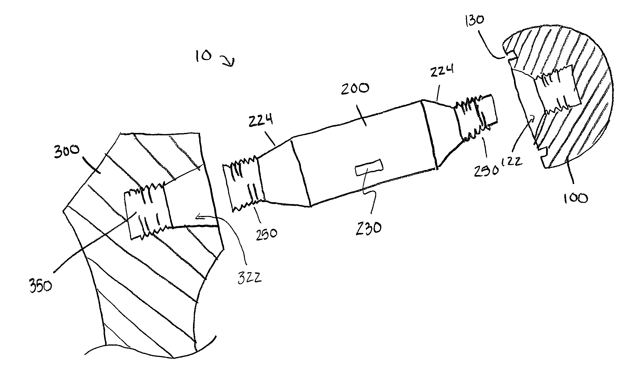
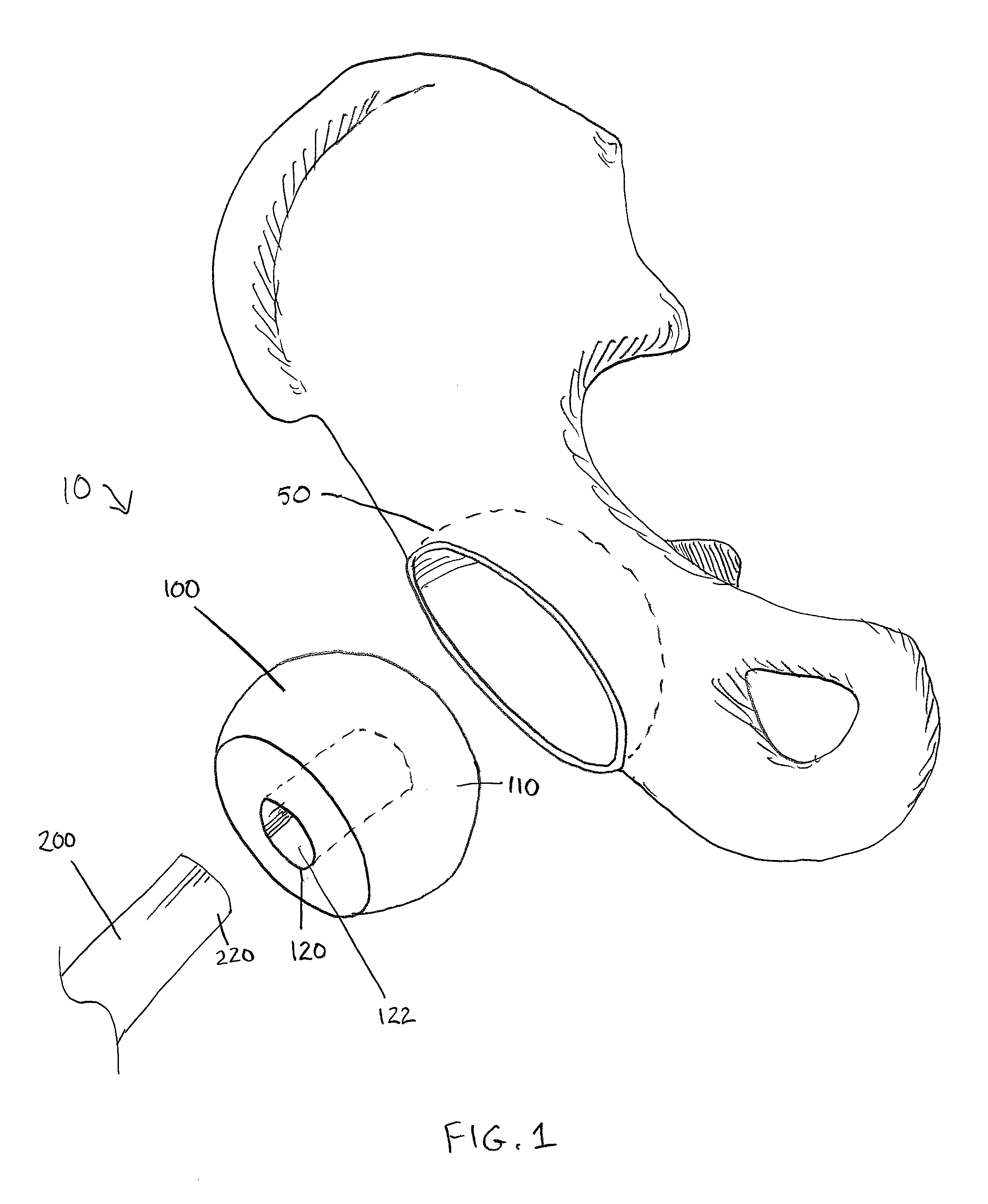
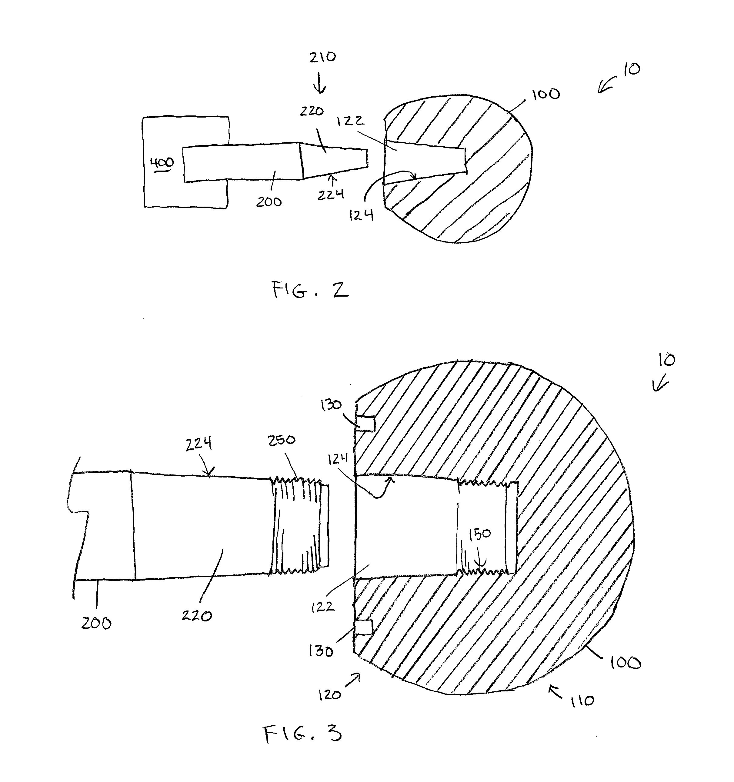
Methods and apparatus for orthopedic replacement of the hip and hip fracture fixation devices include structures and techniques for fixing or enhancing interconnection of implant components, such as by increasing the interconnection in an interference fit with one or more tapers, threads, and / or cooling of components prior to assembly. For example, a prosthetic femoral neck implant can include a thread and a Morse taper for lockable attachment to a prosthetic femoral head and / or intramedullary stem.

Description

CROSS-REFERENCE TO RELATED APPLICATIONS[0001]This application claims the benefit of priority from U.S. Provisional Application No. 61 / 722, 960 filed on Nov. 6, 2012 and is a continuation-in-part of U.S. application Ser. No. 13 / 335,216, filed on Dec. 22, 2011, which is a continuation-in-part of U.S. application Ser. No. 13 / 049,619, filed Mar. 16, 2011 and issued as U.S. Pat. No. 8,211,183, which is a divisional application of U.S. application Ser. No. 12 / 518,081, filed Jun. 5, 2009 and issued as U.S. Pat. No. 8,029,573, which is a U.S. National Phase application of PCT / US2006 / 046795, filed in English on Dec. 7, 2006 and published as WO 2008 / 069800 A1 on Jun. 12, 2008, each of which is incorporated by reference in its entirety herein. Any and all priority claims identified in the Application Data Sheet, or any correction thereto, are hereby incorporated by reference under 37 CFR 1.57.BACKGROUND[0002]1. Field[0003]Embodiments of the present invention relate to medical methods and appar...

Claims


Application Information

Patent Timeline
Patent Type & Authority Patents(United States)
IPC IPC(8): A61F2/32A61F2/30A61F2/36A61F2/46
CPCA61F2/3609A61F2/4637A61F2002/30332A61F2002/30405A61F2002/365A61F2002/3652A61F2002/30334A61F2002/30367A61F2002/4653
Inventor PODOLSKY, ANATOL
Owner IHIP SURGICAL LLC
Learn More