[0009]Therefore, it is an object of the present invention to solve the above-mentioned problem by forming a thin part having a predetermined shape in a part of the elastic arms so that the stiffness decreases only in the direction connecting both ends of the sample and the elastic arms can be easily deformed elastically in the direction, without decreasing the stiffness in the measuring direction of the sample. In this way, an undesirable deformation hardly occurs in the sample. Therefore, the accuracy of the measurement is improved, and the precondition in the calculation step thereafter (that the sample has a rectangular solid shape or a cylindrical column shape) is not broken. Thus, the accuracy of the result is improved.
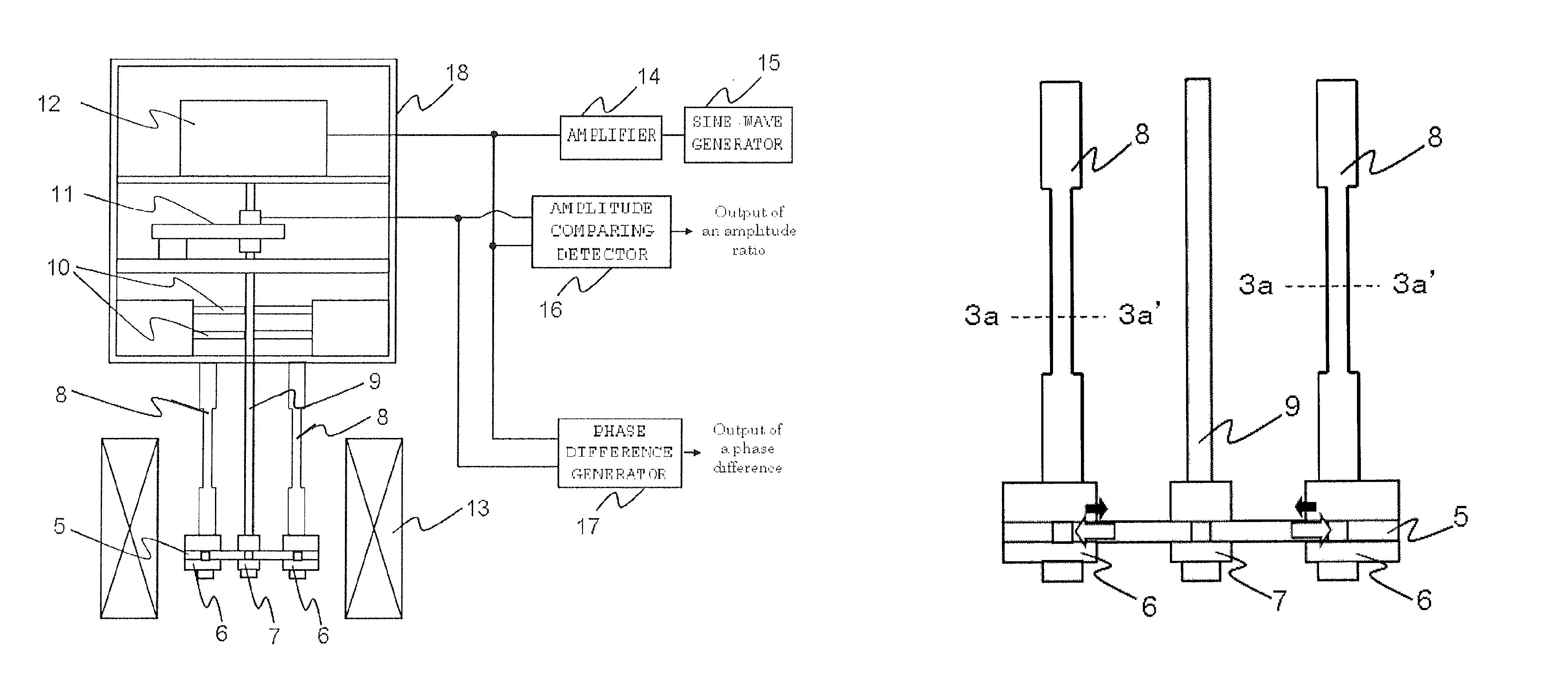
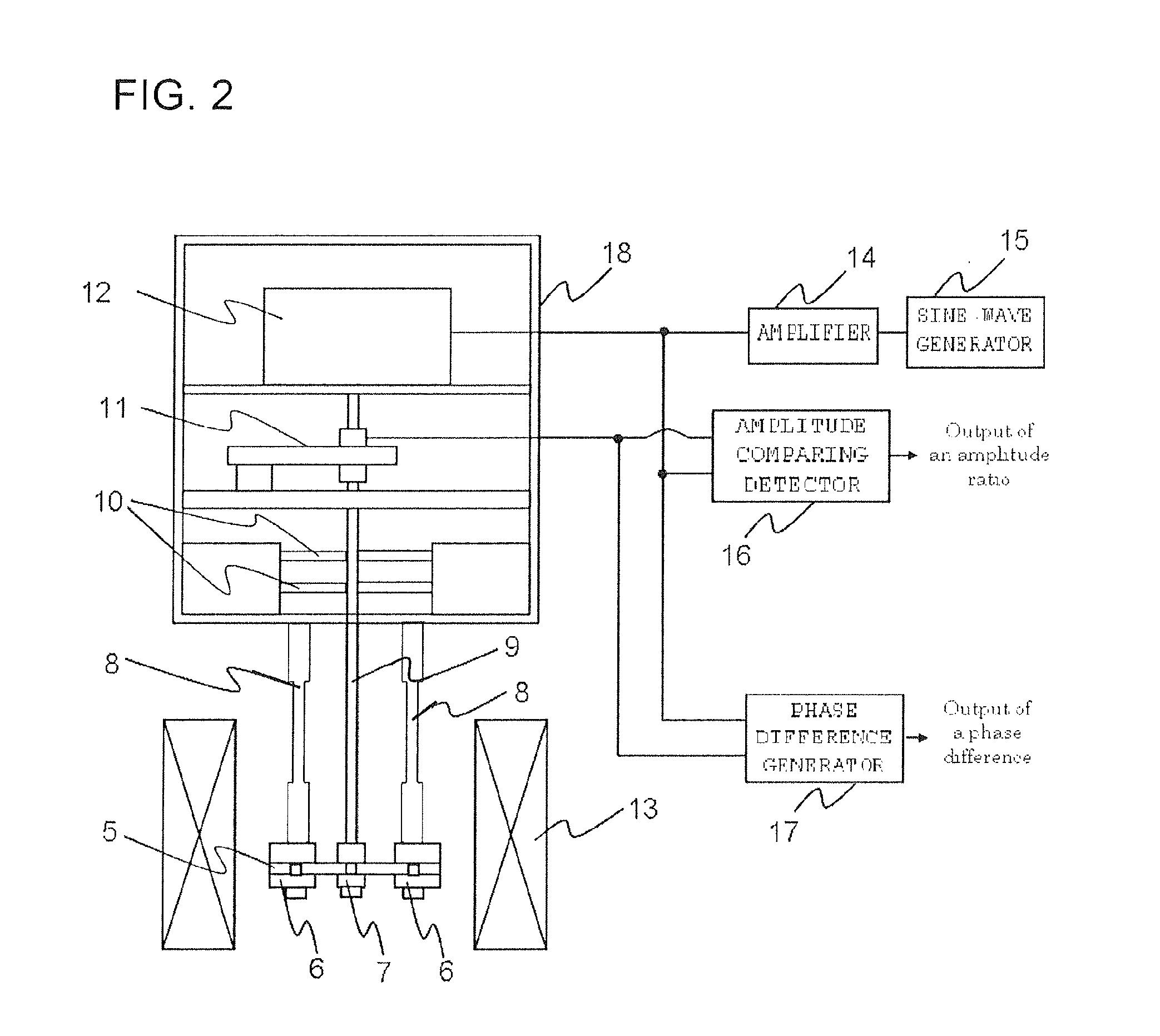
[0010]A viscoelasticity measuring apparatus according to the present invention includes: a chuck that grasps a sample at substantially a central part; a bar-type detection rod that supports the chuck at one end thereof, and is disposed in a thickness direction of the sample; a work effector such as a force generator or a distortion generator disposed at another end of the bar-type detection rod, for applying a load of one of force and distortion to the sample in the thickness direction via the bar-type detection rod and the chuck; a heating source for heating the sample; a sine wave generator that generates a sine wave for causing the force generator to generate work (one of force and distortion) in the form of a sine wave; an amplifier for adjusting an amplitude of the sine wave; a workload detector that is partially fixed to the bar-type detection rod and detects workload of the work; an amplitude comparing detector that compares a signal from the workload detector to a signal from the amplifier so as to output an amplitude ratio; a phase difference detector that compares the signal from the workload detector to the signal from the amplifier so as to output a phase difference; a casing for housing the workload detector and the work effector; a detection rod support member that restricts a movable direction of the bar-type detection rod to a linear direction in the casing and elastically supports the bar-type detection rod; and a sample holder member including a sample holder having a plurality of elastic arms, the plurality of elastic arms having one end fixed to a part of the casing and another end split into at least two portions, the sample holder holding both ends of the sample in the thickness direction, in which the plurality of split elastic arms have thin parts formed in parts thereof so as to suppress deformation of the sample in the direction perpendicular to the direction connecting both ends of the sample. With this structure, even when the sample fixed at both ends by the holder member is expanded by the thermal expansion or the like, the deformation in the viscoelasticity measuring direction is prevented. Therefore, a precondition of a sample shape for calculation of a complex elastic modulus (to be a rectangular solid shape or a cylindrical column shape) is not broken, and it is possible to obtain a result closer to a true value in the measurement. Thus, the complex elastic modulus can be calculated with high accuracy.
[0011]In addition, in the present invention, the elastic arm is split into two or four so that reaction force per elastic arm is reduced, while a necessary function is secured by bundling of a plurality of arms. With this structure, the elastic arm can be easily deformed with respect to a deformation of the sample, and hence an influence to the measurement can be reduced.
[0012]In addition, in the viscoelasticity measuring apparatus according to the present invention, an elasticity modulus as the stiffness of the elastic arm is set in consideration of a decrease in the elasticity modulus of the sample in a temperature range over a glass transition temperature or a softening temperature. With this structure, when an expanding force of the sample rapidly decreases, as the temperature of the sample exceeds the glass transition temperature or the softening temperature, the deformation of the elastic arm does not become a resistance, and hence the accuracy of the measurement can be maintained.
[0014]According to the viscoelasticity measuring apparatus according to the present invention, a predetermined thin part corresponding to the expanding force of the sample is provided in a part of the elastic arm, and hence the elastic arm can easily be warped through the expansion of the sample in the direction connecting both ends, and thus the independent holder members can move more effectively. Consequently, even when heating is performed, the sample shape such as a rectangular solid shape or a cylindrical column can be maintained, and hence an influence in the measuring direction perpendicular to the direction connecting both ends of the sample, which is mostly important at various temperatures, can be reduced. Therefore, the precondition of the sample shape for calculating the complex elastic modulus is not broken, and a measuring error is not generated. Thus, high accuracy calculation can be performed. In addition, because the elastic deformations of the sample holder members and the elastic arms are utilized, the structure becomes simple, and the periphery of the sample can be designed in compact, and hence equal effects can be obtained both in thermal expansion when heating is performed and in thermal contraction when cooling is performed.
[0015]In addition, when the temperature of the sample exceeds the glass transition temperature, the expansion rate increases discontinuously as illustrated in FIG. 6. On the other hand, because the sample is softened, it is necessary for the elastic arm to be warped more easily in the expansion direction of the sample. Therefore, the present invention works more effectively in particular when the measuring viscoelasticity of the sample whose temperature exceeds the glass transition temperature.

