Paper feeding mechanism

Active Publication Date: 2015-03-24
FOXLINK IMAGE TECH
View PDF5 Cites 12 Cited by
  • Summary
  • Abstract
  • Description
  • Claims
  • Application Information

AI Technical Summary

Benefits of technology

[0007]As described above, the drive gear of the gear assembly drives the transmission gear and the gear shaft to rotate to bring along the swing arm to swing and pull the paper pressing tray to raise up to flush with the bottom surface of the paper pressing frame, simultaneously, an elastic potential energy of the elastic element is needed be conquered, the connecting element drives the blocking element to move downward to make the blocking element realize the paper blocking function so as to facilitate placing the paper on the paper supply tray, the drive gear of the gear assembly breaks away from the drive gear, the binding force of the pa

Problems solved by technology

However, the above-mentioned paper feeding mechanism realizes the paper feeding function by virtue of the gear assembly transmitting the driving force generated by a plurality of mot

Method used


Image

  • Paper feeding mechanism
  • Paper feeding mechanism
  • Paper feeding mechanism

Examples


Example

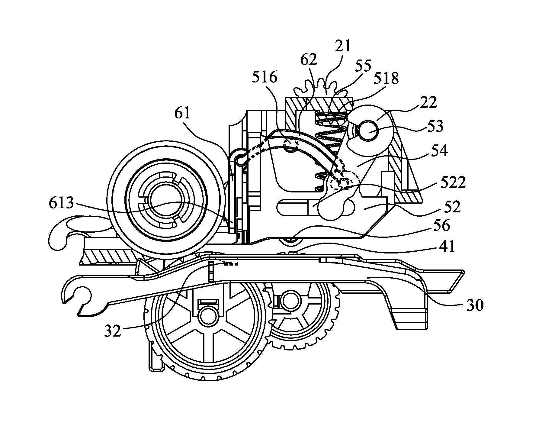
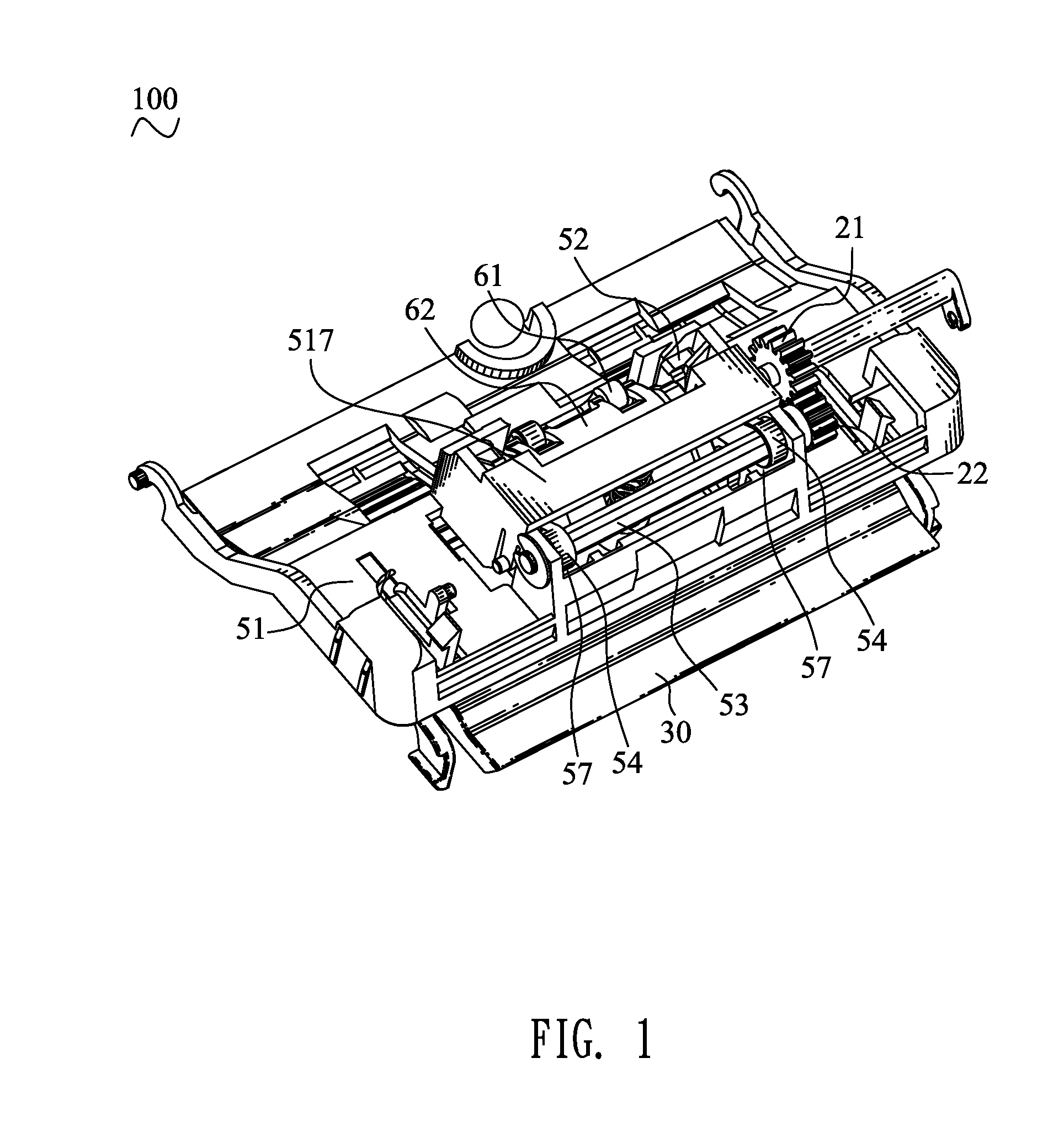
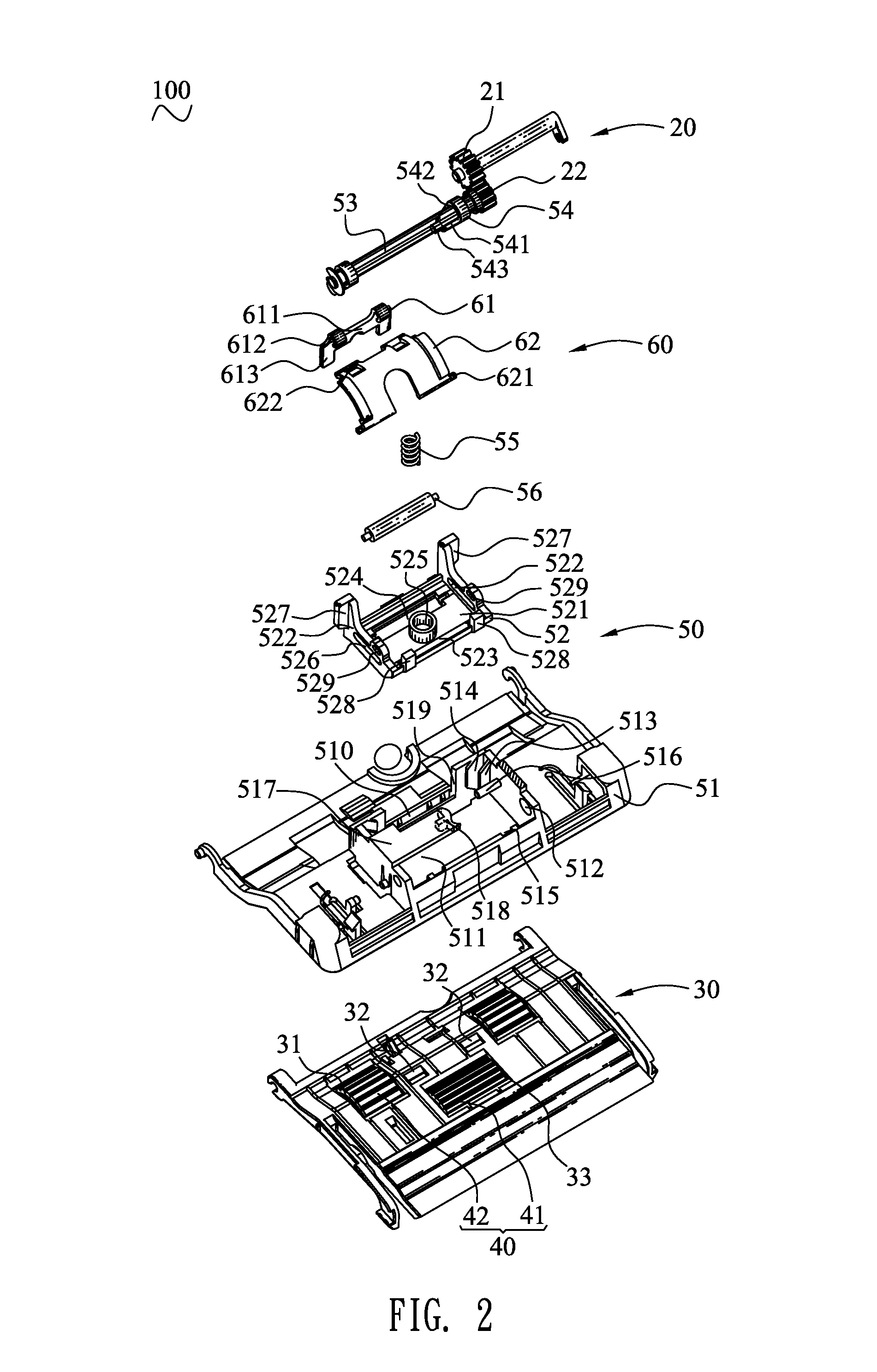
[0013]With reference to FIG. 1 to FIG. 4, a paper feeding mechanism 100 in accordance with an embodiment of the present invention is shown. The paper feeding mechanism 100 driven by a driving device (not shown), includes a mechanical frame (not shown), a gear assembly 20, a paper supply tray 30, a pickup assembly 40, a paper pressing assembly 50 and a stopper assembly 60 (not shown). The gear assembly 20, the paper supply tray 30, the pickup assembly 40, the paper pressing assembly 50 and the stopper assembly 60 are mounted to the mechanical frame. The gear assembly 20 transmits driving force generated by the driving device to the pickup assembly 40, the paper pressing assembly 50 and the stopper assembly 60 to realize a paper feeding function. In this embodiment, the driving device is designated as one motor.

[0014]Referring to FIG. 2, the gear assembly 20 is mounted to one side of the mechanical frame. The gear assembly 20 includes a drive gear 21 driven by the driving device, and ...


PUM


Abstract

A paper feeding mechanism includes a mechanical frame, a gear assembly, a paper supply tray, a pickup assembly, a paper pressing assembly and a stopper assembly. The gear assembly includes a drive gear and a transmission gear. The paper pressing assembly includes a paper pressing frame, a paper pressing tray, a gear shaft, at least one swing arm and an elastic element. The stopper assembly includes a blocking element and a connecting element. The drive gear drives the transmission gear and the gear shaft to rotate, the connecting element drives the blocking element to move downward to make the blocking element realize a paper blocking function, and the drive gear breaks away from the drive gear, the elastic element pushes against the paper pressing tray to move downward, the blocking element breaks away from the paper supply tray to raise up for making the paper blocking function disappeared.

Description

BACKGROUND OF THE INVENTION[0001]1. Field of the Invention[0002]The present invention generally relates to a paper feeding mechanism, and more particularly to a paper feeding mechanism with a paper blocking function.[0003]2. The Related Art[0004]A traditional paper feeding mechanism driven by a driving device (not shown), includes a mechanical frame, a paper supply tray, a gear assembly, a pickup assembly, a paper pressing assembly and a stopper assembly. The paper supply tray, the gear assembly, the paper pressing assembly and the stopper assembly are respectively mounted to the mechanical frame. The pickup assembly is assembled to the mechanical frame and the paper supply tray. The gear assembly transmits driving force generated by the driving device to the pickup assembly, the paper pressing assembly and the stopper assembly to realize a paper feeding function. The driving device is designated as a plurality of motors.[0005]However, the above-mentioned paper feeding mechanism rea...

Claims


Application Information

Patent Timeline
IPC IPC(8): B65H3/34B65H1/04B65H3/56B65H9/04B65H9/06
CPCB65H1/04B65H3/56B65H9/06B65H9/04B65H1/12B65H3/063B65H3/34B65H2403/42B65H2403/5331B65H2402/31B65H2402/32B65H2402/54
Inventor FANG, JING HUALIAO, WEN CHINGHONG, I CHUAN
Owner FOXLINK IMAGE TECH
Why Eureka
Try Eureka