Inter-terminal connection structure

a technology of inter-terminal connection and connector, which is applied in the direction of coupling device connection, coupling contact member, coupling device details, etc., can solve the problems of deteriorating contact reliability between the plug terminal and the receptacle terminal, damage to the plug terminal, and difficult to prevent, so as to prevent the damage to the connection terminal and good connection state

Inactive Publication Date: 2015-03-24
HIROSE ELECTRIC GROUP
View PDF49 Cites 3 Cited by
  • Summary
  • Abstract
  • Description
  • Claims
  • Application Information

AI Technical Summary

Benefits of technology

[0020]As described above, according to the first aspect of the present invention, in the inter-terminal connection structure, the contact pieces and the locking pieces do not have the mixed range in the longitudinal direction, and the locking pieces regulate the connection terminal in the non-sandwiched state. Accordingly, when the board terminal and the conductive member are shifted from the standard position, the connection terminal is moved only to an inclined state relative to the standard position (the position where the connection terminal extends in the arrangement direction) in the terminal width direction while following the shift with the position of the corresponding contact portions sandwiched with the contact portions of the board terminal as a pivot, so that the connection terminal is not elastically deformed. As a result, a stress is not applied to the connection terminal, thereby preventing the connection terminal from being damaged. Further, it is possible to securely maintain the good connection state between the connection terminal and the board terminal.
[0022]According to the second aspect of the present invention, the board terminal having an identical configuration is disposed on each of the two circuit boards. A circuit portion of the other of the circuit boards corresponds to the conductive member. The contact portions of the board terminals on the circuit boards are connected through the plate shape portion of the connection terminal of the connection connector. When one of the circuit boards and the other one of the circuit boards are shifted from a standard position, the connection terminal is inclined and moved to a position on a line between the contact portions of the board terminals on the two circuit boards without being elastically deformed. Accordingly, the locking portion enters the locked portion, so that it is possible to maintain the state capable of locking without a pressing force.
[0024]According to the third aspect of the present invention, the locked portion is situated closer to the edge portion of the circuit board than the contact pieces. Accordingly, when the board terminal is shifted from the standard position, even if the locked portion is situated on the same inclined line as the contact portions, the locked portion is moved for a distance smaller than a deformation amount of the contact portions of the board terminal, thereby making it possible to prevent the locking pieces from coming off.
[0033]As described above, according to the present invention, when the board terminal and the conductive member are shifted from the standard position, the connection terminal is moved only to an inclined state relative to the standard position in the terminal width direction while following the shift with the position of the corresponding contact portions sandwiched with the contact portions of the board terminal as a pivot, so that the connection terminal is not elastically deformed. As a result, a stress is not applied to the connection terminal, thereby preventing the connection terminal from being damaged. Further, it is possible to securely maintain the good connection state between the connection terminal and the board terminal.

Problems solved by technology

Accordingly, as long as the connection state is maintained, in which the plug terminal is deformed elastically to absorb the shift of the receptacle terminals, a stress is applied to the plug terminal for a long period of time due to the elastic deformation, thereby causing damage in the plug terminal.
Further, when the plug terminal is deformed elastically, it is difficult to maintain the connection state between the plug terminal and the receptacle terminals, thereby deteriorating contact reliability between plug terminal and the receptacle terminals.
Further, in the conventional inter-terminal connection structure disclosed in Patent Reference, even when a cable or the plug terminal having other conductive member is connected to the receptacle terminal mounted on the circuit board as the board terminal, it is difficult to prevent the problem due to the elastic deformation of the plug terminal in the connection state, as far as the first sandwiching pieces and the second sandwiching pieces of the receptacle terminal press against and contact with the both surfaces of the plug terminal at the different locations in the arrangement direction.

Method used


Image

  • Inter-terminal connection structure
  • Inter-terminal connection structure
  • Inter-terminal connection structure

Examples


Embodiment Construction

[0040]Hereunder, embodiments of the present invention will be explained with reference to the accompanying drawings. In the accompanying drawings, similar components are designated with the same reference numerals, and repeated explanations thereof are omitted.

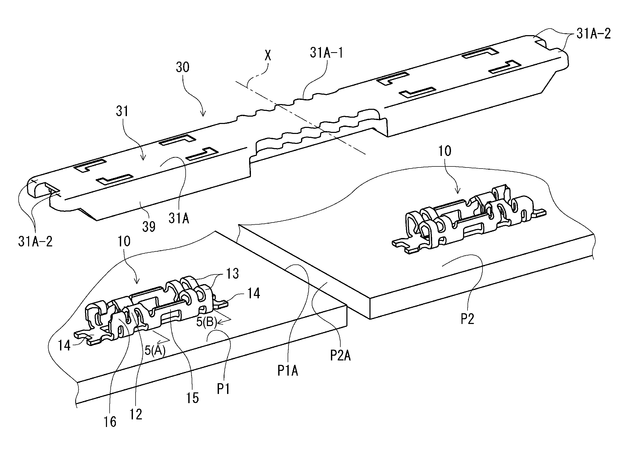
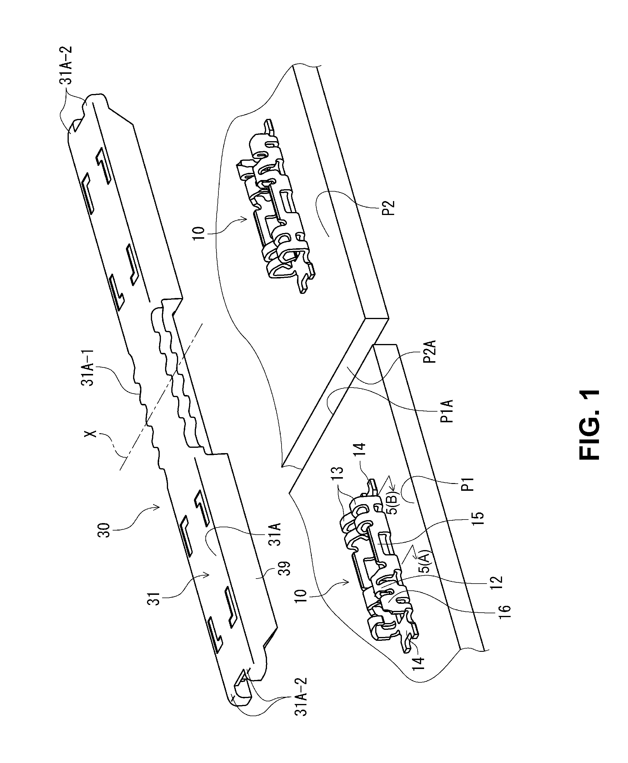
[0041]FIG. 1 is a perspective view showing a board terminal 10 and a connection connector 30 of an inter-terminal connection structure just before the board terminal 10 is connected to the connection connector 30 according to an embodiment of the present invention.

[0042]As shown in FIG. 1, the board terminals 10 having an identical configuration are mounted on two circuit boards P1 and P2 such that the board terminals 10 are connected to corresponding circuit portions (not shown) on the circuit boards P1 and P2. Further, the connection connector 30 is to be connected to the board terminals 10 in a state that edge portions P1A and P2A of the circuit boards P1 and P2 face each other, so that the connection connector 30 connects ...


PUM


Abstract

An inter-terminal connection structure includes a circuit board terminal to be mounted on a circuit board; and a connection connector for connecting the circuit board terminal. The circuit board terminal includes a base portion, a pair of contact pieces extending from the base portion, and a pair of locking pieces extending from the base portion. Each contact pieces includes an elastic arm portion, and each locking pieces includes a locking portion having a locking protrusion. The connection connector includes a connection terminal having a plate shape portion sandwiched between the contact pieces and the locking pieces, and a housing that holds the connection terminal. The plate shape portion includes a locked portion, so that the locking protrusion is situated in the locked portion with a play to be movable when the connection connector is attached to the circuit board terminal.

Description

BACKGROUND OF THE INVENTION AND RELATED ART STATEMENT[0001]The present invention relates to an inter-terminal connection structure, and a board terminal and a connection connector thereof. More specifically, the present invention relates to an inter-terminal connection structure for electrically connecting a conductive member to be connected to a connection connector to a board terminal mounted on a circuit board through a connection terminal of the connection connector.[0002]Patent Reference has disclosed a conventional inter-terminal connection structure. In the inter-terminal connector structure disclosed in Patent Reference, a receptacle terminal (a board terminal) is mounted on each of two circuit boards placed on a same level plane. A plug connector provided with a plug terminal (a connection terminal) having a plate shape is configured to connect the receptacle terminals in a state that the receptacle terminals are arranged along one direction, so that the receptacle terminal...

Claims


Application Information

Patent Timeline
Patent Type & Authority Patents(United States)
IPC IPC(8): H01R12/00H01R11/01H01R12/71H01R12/73H01R13/11
CPCH01R11/01H01R12/718H01R12/732H01R13/11Y10S439/952
Inventor ISHII, KENTARO
Owner HIROSE ELECTRIC GROUP
Why Eureka
Try Eureka