Shielded connector

a shielding connector and connector technology, applied in the direction of electrical equipment, connection, coupling device connection, etc., can solve problems such as wire breakage, and achieve the effect of good connection state and sufficient fixation strength

Active Publication Date: 2013-12-26
YAZAKI CORP
View PDF2 Cites 2 Cited by
  • Summary
  • Abstract
  • Description
  • Claims
  • Application Information

AI Technical Summary

Benefits of technology

[0012]Therefore, a sufficient fixation strength in the crimping portion is obtained without increasing a crimping force, and a compression of the inner conductor at the crimping position caused by increasing the crimping force is inhibited as far as possible. As a result, the shielded connector is connected to the shielded electrical cable without problems, such as breaking of the inner conductor.
[0013]According to the present invention, a shielded connector, which is pressed against a shielded electrical cable without problems and thus achieve a good connection state, is provided.

Problems solved by technology

In addition, if a crimping force of the shield conductor crimping portion 116 is increased to obtain a fixation strength, the signal conductor 101 of the shielded electrical cable 105 at the crimping position is strongly compressed, and thus there is a possibility of causing problems, such as breaking of a wire.

Method used


Image

  • Shielded connector
  • Shielded connector
  • Shielded connector

Examples


Embodiment Construction

[0023]An example of an embodiment of the present invention will be now described with reference to the accompanying drawings.

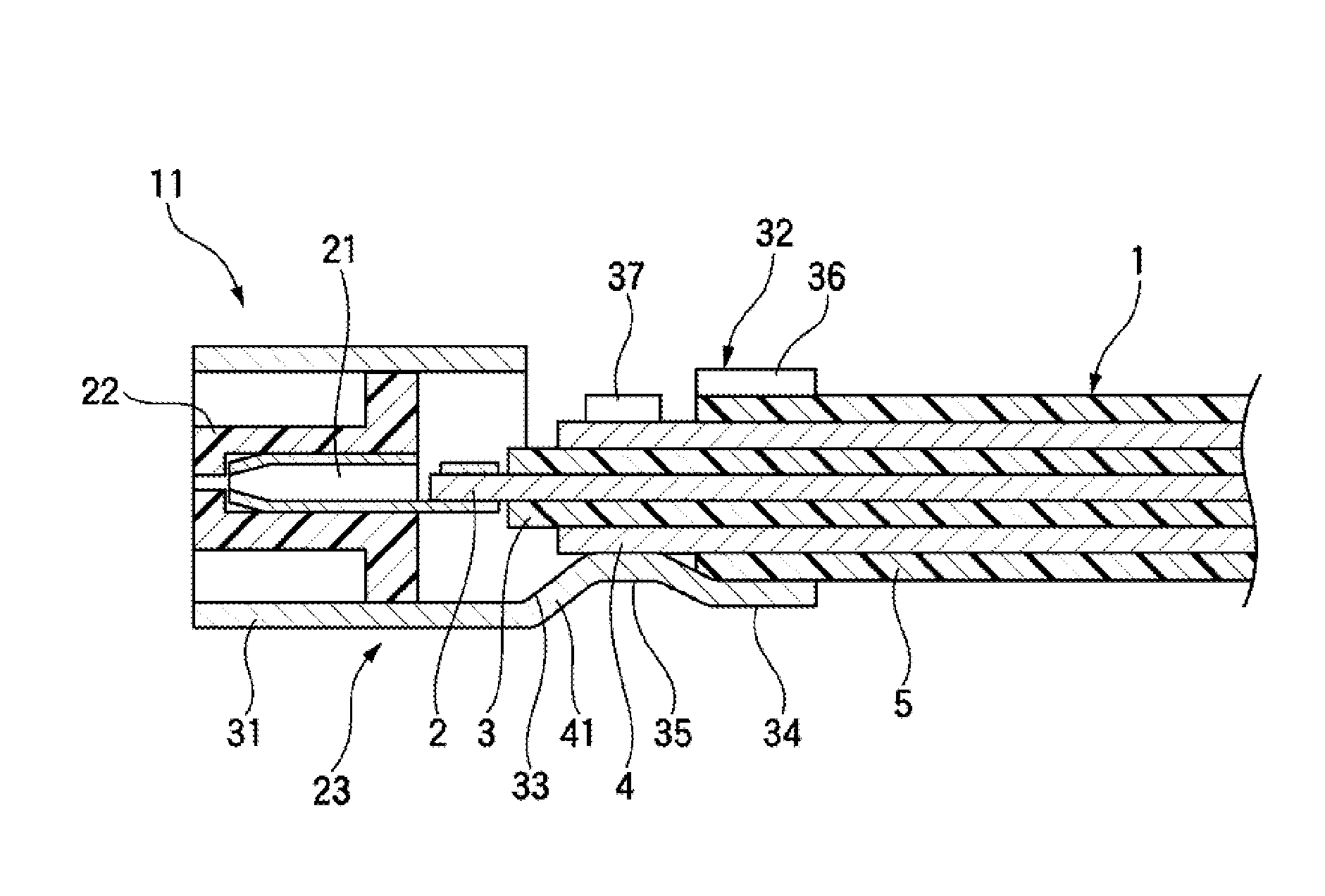
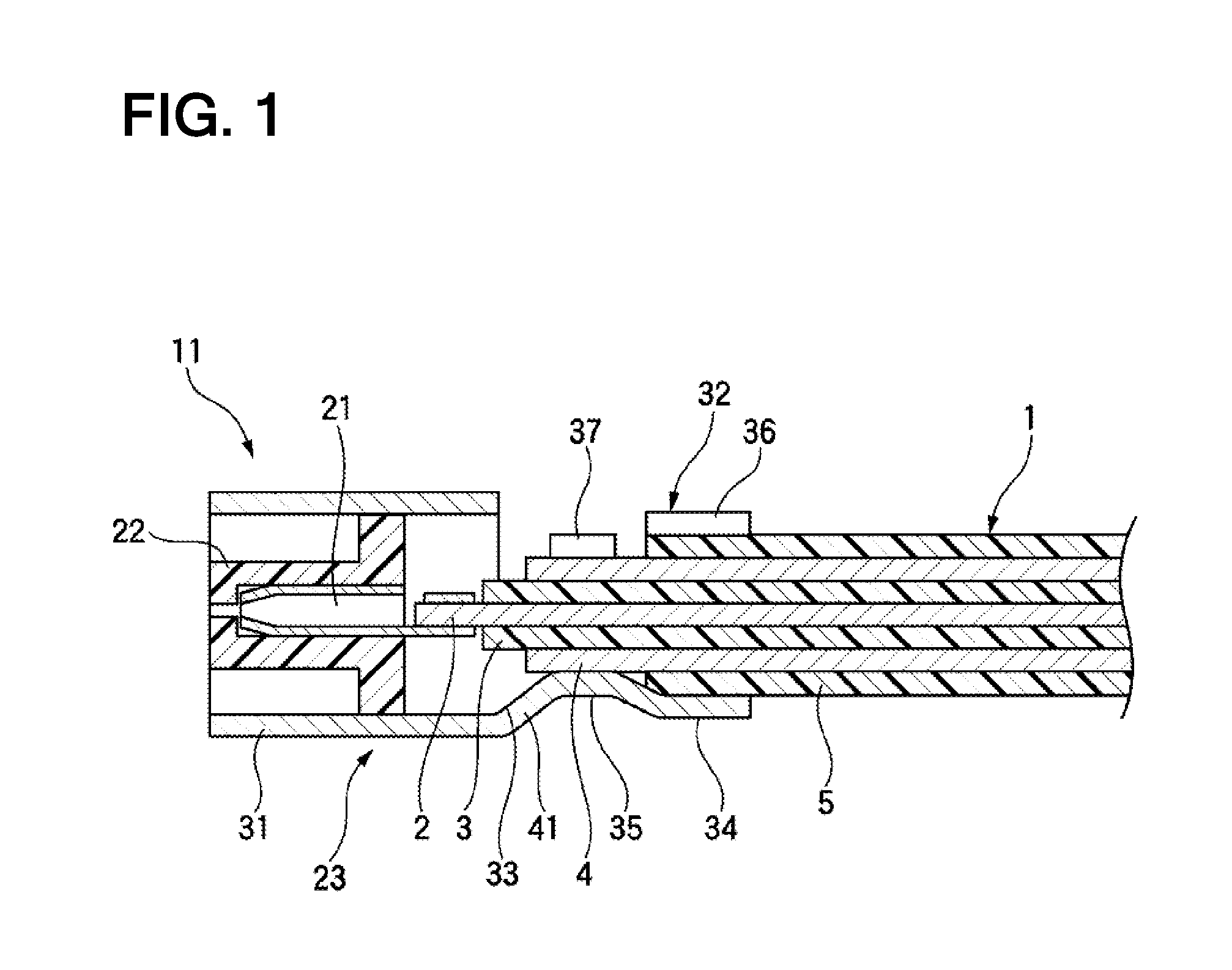
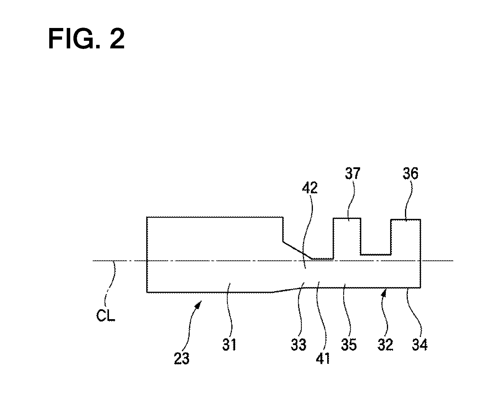
[0024]FIG. 1 is a sectional view showing a shielded connector according to the present embodiment, FIG. 2 is a side view showing an outer terminal constituting the shielded connector according to the embodiment, FIG. 3 is a plan view showing the shielded connector according to the embodiment connected to a shielded electrical cable, and FIG. 4 is a side view showing the shielded connector according to the embodiment connected to the shielded electrical cable.

[0025]As shown in FIG. 1, the shielded connector 11 according to the present embodiment is connected to a terminal of the shielded electrical cable 1. The shielded electrical cable 1 includes an inner conductor 2, an insulator 3 extending in a longitudinal direction of the inner conductor 2 while surrounding an outer circumferential surface of the inner conductor 2, an outer conductor 4 extending in the lo...


PUM


Abstract

A shielded connector adapted to be connected to a terminal of a shielded electrical cable provided with an insulator, an outer conductor and a sheath around an inner conductor in this order includes an inner terminal that is connected to the inner conductor, an insulating member that covers the inner terminal, and an outer terminal that is connected to the outer conductor. The outer terminal includes a cylindrical-shaped shield portion that covers the insulating member, a crimping portion, and a connection portion that connects the shield portion with the crimping portion. The connection portion includes a bottom plate part and side wall parts erected from both sides of the bottom plate part, and the side wall parts have upper ends having a height equal to or larger than a center line of the outer terminal.

Description

CROSS REFERENCE TO RELATED APPLICATION[0001]This application is based on Japanese Patent Applications No. 2012-139019 filed on Jun. 20, 2012, the contents of which are incorporated herein by reference.BACKGROUND OF THE INVENTION[0002]1. Technical Field[0003]The present invention relates to a shielded connector adapted to be connected to a shielded electrical cable.[0004]2. Background Art[0005]As shown in FIG. 5, a shielded connector 111 adapted to be connected to a shielded electrical cable 105, in which a shield conductor 103 is covered around a signal conductor 101 with an insulator 102 interposed therebetween and a sheath 104 is coved around an outer circumference of the shield conductor 103, is known (see JP-A-2006-310135). In the shielded connector 111, an inner conductor terminal 112 is connected to a terminal of the signal conductor 101, the inner conductor terminal 112 is received in a generally cylindrical-shaped tubular receiving portion 115 of an outer conductor terminal ...

Claims


Application Information

Patent Timeline
Patent Type & Authority Applications(United States)
IPC IPC(8): H01R13/6592
CPCH01R13/6592H01R4/185H01R9/0518
Inventor KANDA, HIDENORI
Owner YAZAKI CORP
Why Eureka
Try Eureka