
Display device with light guide plate having irregularities on front light exit surface

a technology of light guide plate and exit surface, which is applied in the direction of lighting and heating apparatus, instruments, mechanical equipment, etc., can solve the problem that the light that is supposed to be reflected at the interface on the rear surface of the light guide plate is absorbed by the reflective sh

Active Publication Date: 2015-03-31
JAPAN DISPLAY INC
View PDF9 Cites 2 Cited by
  • Summary
  • Abstract
  • Description
  • Claims
  • Application Information

AI Technical Summary

Benefits of technology

[0007]The present invention has an object to provide a display device including a light guide plate, which is capable of causing light to exit efficiently while causing light convergence, regardless of a change in brightness distribution due to an intimate contact with respect to a reflective sheet.
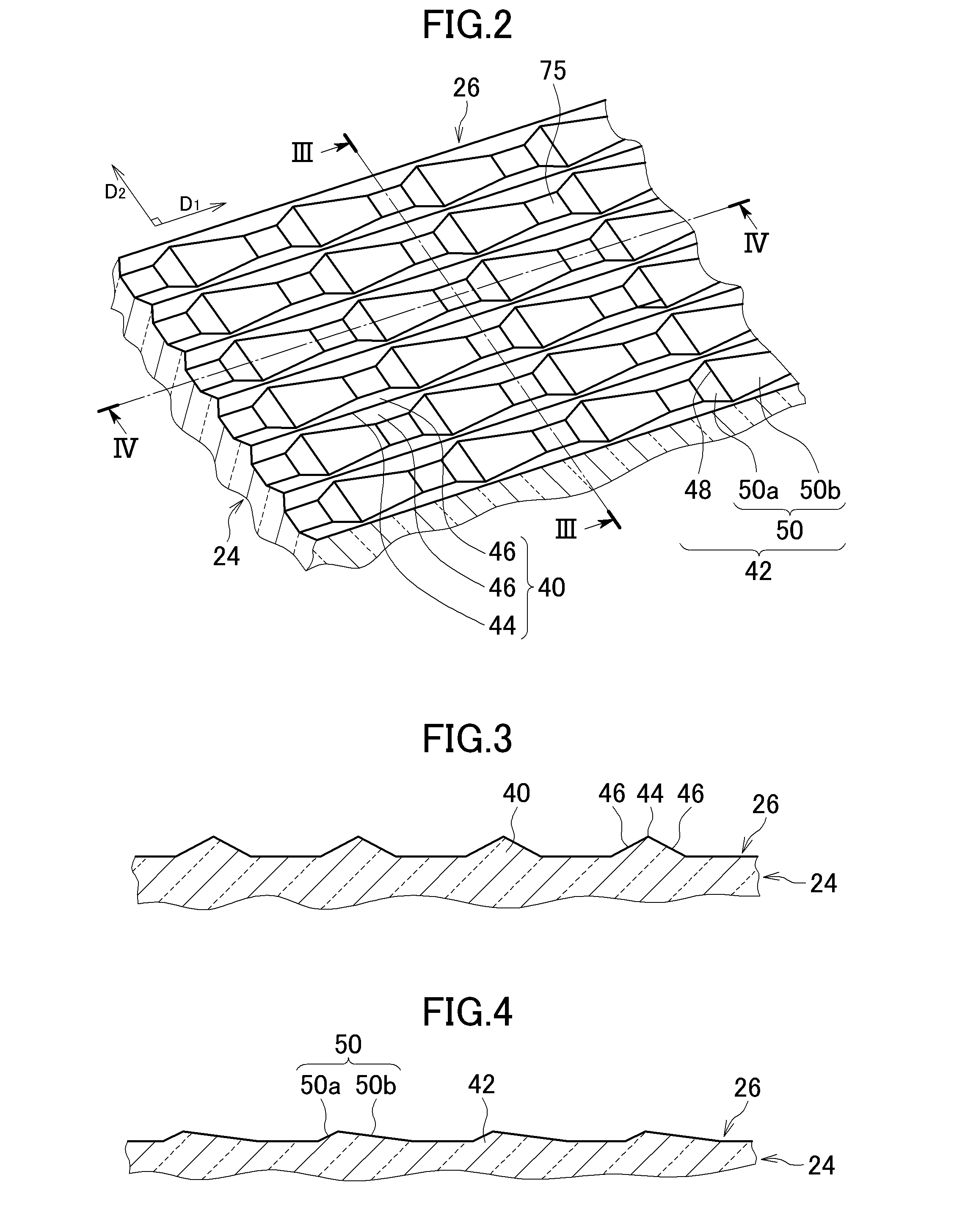
[0008](1) A display device according to an exemplary embodiment of the present invention includes: a light source; a light guide plate including a front surface, a rear surface on a side opposite to the front surface, and an edge surface connecting the front surface and the rear surface to each other, the light guide plate being arranged so that the edge surface is opposed to the light source, the light guide plate being configured to internally reflect light entering from the edge surface to cause planar light emission from the front surface; a light shutter type display panel, which is arranged so as to be opposed to the front surface of the light guide plate, and in which passing and blocking of the light exiting from the front surface of the light guide plate is controlled to display an image; and a reflective sheet arranged so as to be opposed to the rear surface of the light guide plate. The front surface has irregularities formed thereon. The irregularities are formed to have a shape of a combination of a plurality of first convex portions and a plurality of second convex portions, each of the plurality of first convex portions including a first ridge line which continuously extends along a first direction corresponding to a traveling direction of the light, each of the plurality of second convex portions including a second ridge line which continuously extends along a second direction intersecting the first direction. According to the present invention, the irregularities are formed on the front surface from which light exits, and hence it is possible to cause light to exit efficiently while causing light convergence, regardless of the change in brightness distribution due to the intimate contact between the rear surface and the reflective sheet.
[0011](4) A display device according to another exemplary embodiment of the present invention includes: a light source; a light guide plate including a front surface, a rear surface on a side opposite to the front surface, and an edge surface connecting the front surface and the rear surface to each other, the light guide plate being arranged so that the edge surface is opposed to the light source, the light guide plate being configured to internally reflect light entering from the edge surface to cause planar light emission from the front surface; a light shutter type display panel, which is arranged so as to be opposed to the front surface of the light guide plate, and in which passing and blocking of the light exiting from the front surface of the light guide plate is controlled to display an image; and a reflective sheet arranged so as to be opposed to the rear surface of the light guide plate. The front surface has irregularities formed thereon. The irregularities are formed to have a shape of a combination of a plurality of first concave portions and a plurality of second concave portions, each of the plurality of first concave portions including a first valley line which continuously extends along a first direction corresponding to a traveling direction of the light, each of the plurality of second concave portions including a second valley line which continuously extends along a second direction intersecting the first direction. According to the present invention, the irregularities are formed on the front surface from which light exits, and hence it is possible to cause light to exit efficiently while causing light convergence, regardless of the change in brightness distribution due to the intimate contact between the rear surface and the reflective sheet.
[0014](7) In the display device according to any one of the above-mentioned items (1) to (6), the reflective sheet may include an enhanced specular reflector.

Problems solved by technology

However, because the reflective sheet can be brought into intimate contact with the light guide plate, there arises a problem that light that is supposed to be reflected at the interface on the rear surface of the light guide plate is absorbed in the reflective sheet.

Method used


Image

  • Display device with light guide plate having irregularities on front light exit surface
  • Display device with light guide plate having irregularities on front light exit surface
  • Display device with light guide plate having irregularities on front light exit surface

Examples


Embodiment Construction

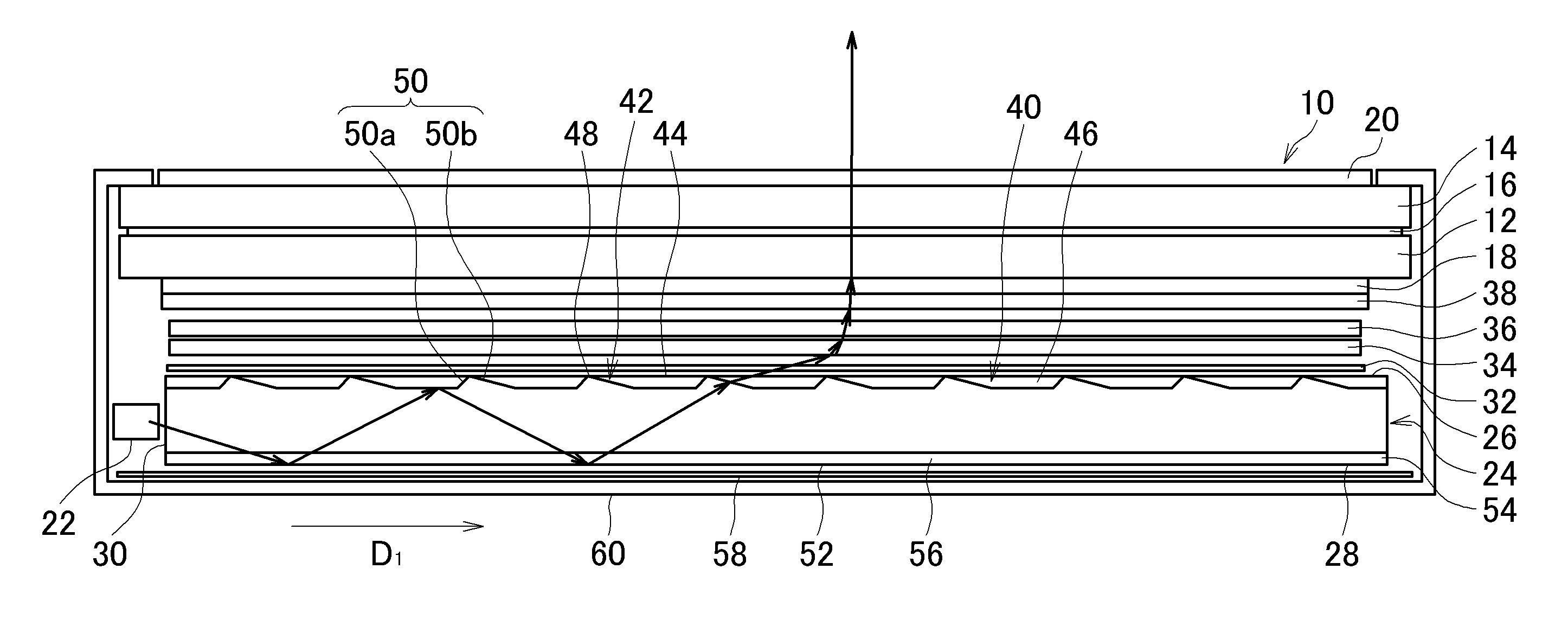
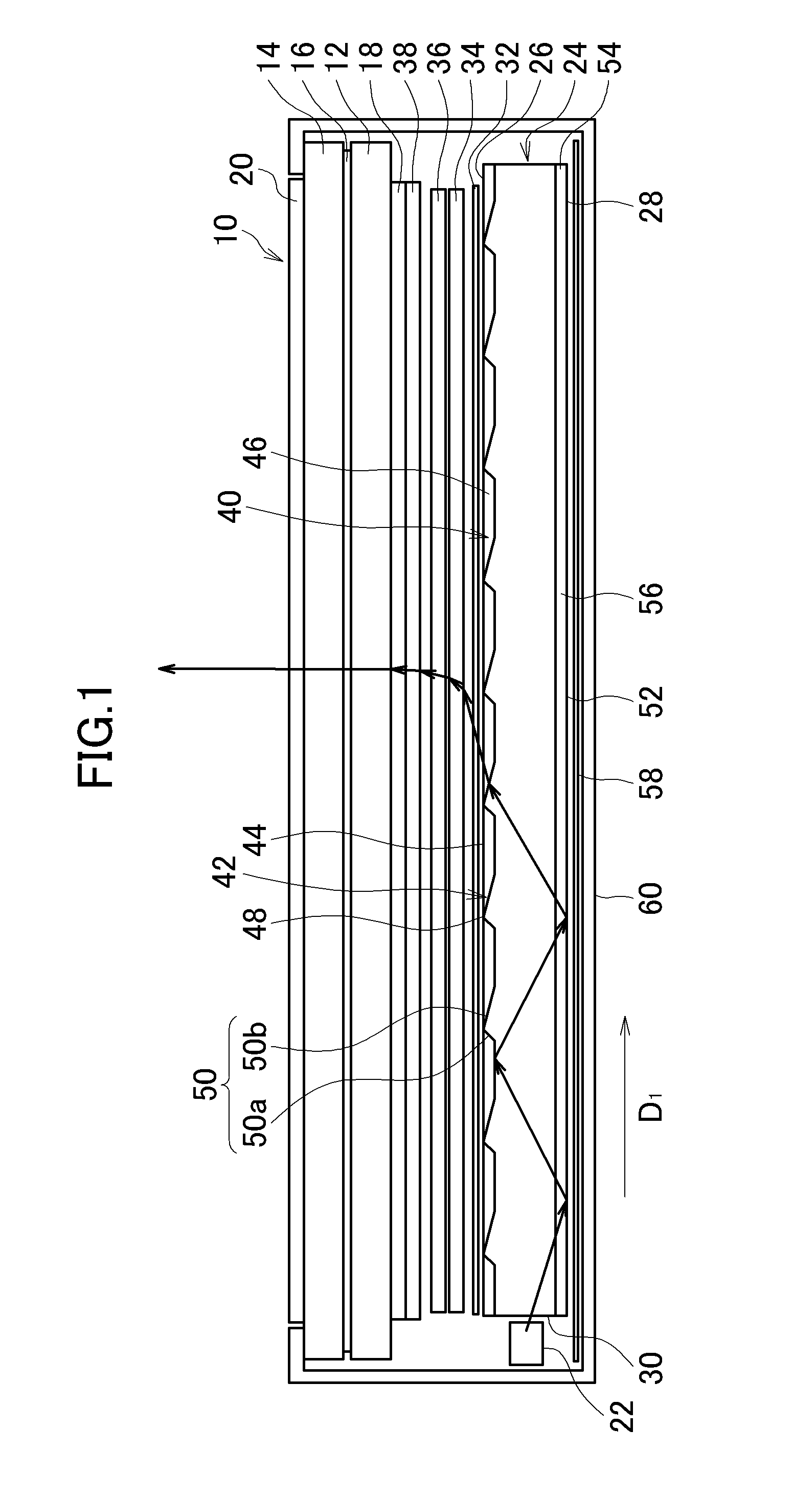
[0034]Hereinafter, an embodiment of the present invention is described with reference to the drawings. FIG. 1 is a sectional view illustrating a display device according to the embodiment of the present invention.

[0035]The display device includes a display panel 10. The display panel 10 is a light shutter type display panel in which passing and blocking of light is controlled to display an image. The display panel 10 illustrated in FIG. 1 is a liquid crystal display panel. The display panel 10 includes a pair of substrates 12 and 14 each made of, for example, glass, a liquid crystal layer 16 sandwiched therebetween, and polarizing plates 18 and 20 respectively provided on outer sides of the pair of substrates 12 and 14.

[0036]The display device includes a light source 22. The light source 22 is a point light source such as a light emitting diode (LED) or a linear light source.

[0037]The display device includes a light guide plate 24. The light guide plate 24 includes a front surface 2...


PUM


Abstract

Provided is a display device including: a light guide plate arranged so that an edge surface thereof is opposed to a light source, the light guide plate being configured to internally reflect light entering from the edge surface to cause planar light emission from a front surface of the light guide plate; and a reflective sheet arranged so as to be opposed to a rear surface of the light guide plate. Irregularities are formed on the front surface. The irregularities are formed to have a shape of a combination of first convex portions and second convex portions, each of the first convex portions including a first ridge line which continuously extends along a first direction corresponding to a light traveling direction, each of the second convex portions including a second ridge line which continuously extends along a second direction intersecting the first direction.

Description

CROSS-REFERENCE TO RELATED APPLICATION[0001]The present application claims priorities from Japanese applications JP 2011-θ20364 filed on Feb. 2, 2011 and JP 2011-133944 filed on Jun. 16, 2011, the contents of which are hereby incorporated by reference into those applications.BACKGROUND OF THE INVENTION[0002]1. Field of the Invention[0003]The present invention relates to a display device.[0004]2. Description of the Related Art[0005]In a liquid crystal display device including an edge-lit backlight unit, light entering an edge surface of a light guide plate travels inside the light guide plate, and is reflected at an interface on a rear surface side of the light guide plate to exit from a front surface thereof (see Japanese Patent Application Laid-open No. 2009-276531). Specifically, on the rear surface side, mountain-like convex portions or valley-like concave portions are formed so that ridge lines thereof extend in a direction orthogonal to the traveling direction of light. Light r...

Claims


Application Information

Patent Timeline
Patent Type & Authority Patents(United States)
IPC IPC(8): F21V7/04F21V8/00
CPCG02B6/0038G02B6/0055G02B6/00G02F1/1335
Inventor OKU, KENTAROSHIRAISHI, YASUHISAUEHARA, MASAOTOBE, AKIYOSHIKUWABARA, TAKASHI
Owner JAPAN DISPLAY INC
Learn More