[0006]According to the invention, the hot air welding nozzle has at least one front outlet relative to the moving direction of the hot air welding device. That has the effect that the entire effective heating zone where the webs of sealing material are pre-heated and then plasticized for the
welding process is significantly enlarged. In already pre-heated condition, the webs of sealing material reach the heat plates where the outlets are preferably distributed evenly over the entire surface; after passing the heat plate, they reach the rear outlet where they are sufficiently plasticized for the subsequent
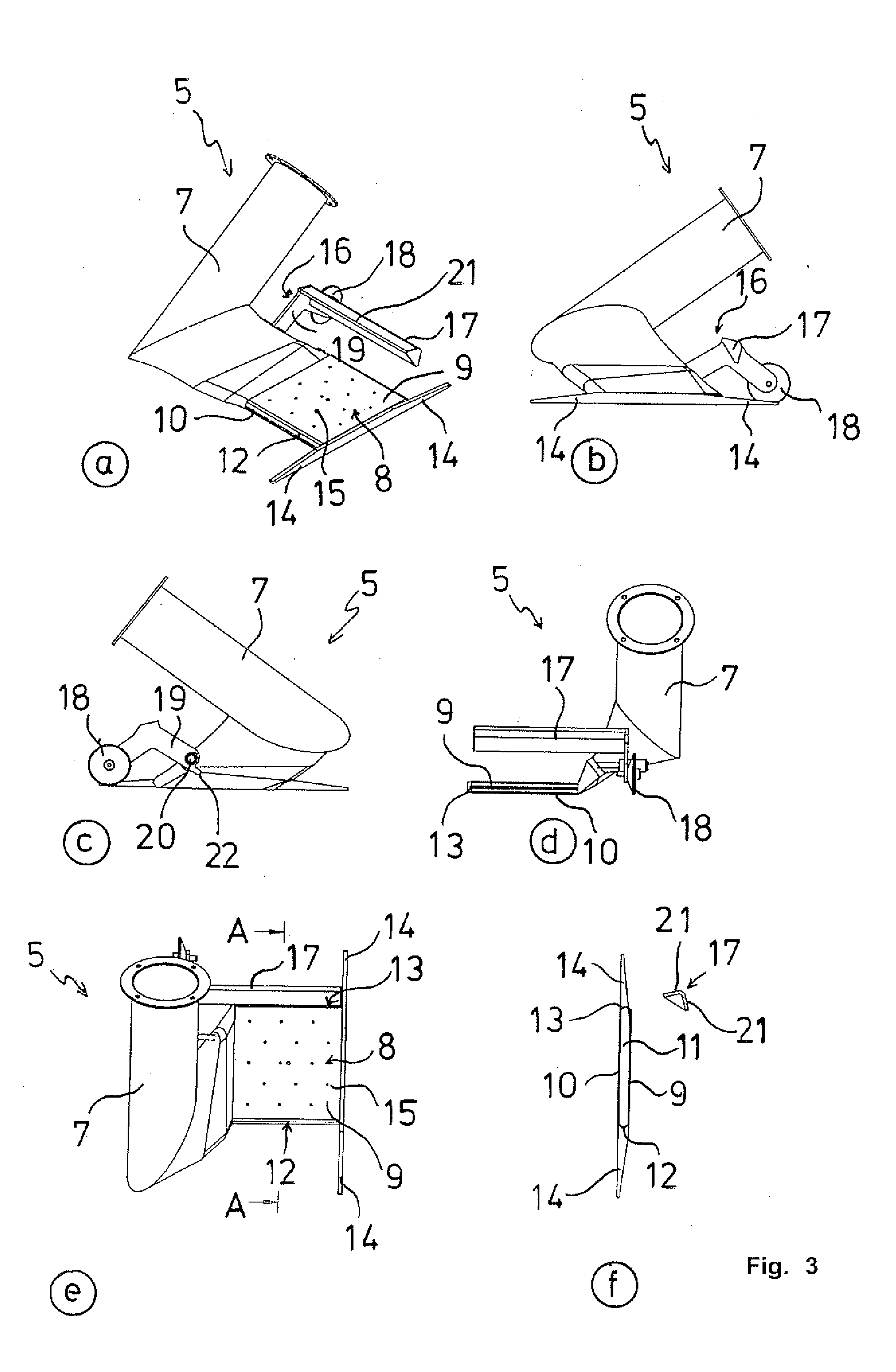
welding process. The front as well as the rear outlet may be designed as slots with one opening, or, with interruptions, as several openings or holes that extend in familiar fashion across the entire width of the nozzle. In order to prevent the hot air exiting from the front and rear outlets from passing beyond the edge of the bottom film between the webs of sealing material, thereby destroying the insulating layer underneath, air guides extending beyond the faces of the heat plate are mounted on the hot air welding nozzle, at least on the inner side, the one facing away from the connection for the hot air supply. These air guides prevent the hot air from reaching undesirable areas and ensure that the hot air remains precisely in the zone that is important for the welding process.
[0007]According to a further embodiment of the invention, the top and the bottom heat plate are essentially parallel. As a consequence, the rear outlet as well as the front outlet have a uniform air outlet area, preferably across the entire width of the hot air welding nozzle, thereby achieving a more uniform air distribution than the familiar triangular outlet openings. In addition, the heat plates may have outlets that are preferably distributed evenly, thereby generating a hot
air cushion between the top heat plate and the top web of sealing material. In this way, the top web of sealing material contacts, in part, the top heat plate, while, on the other hand, the hot air exiting from the outlets becomes effective. Beside the hot surface of the heat plate, the exiting hot air also has a
heating effect on the web of sealing material.
[0008]It offers advantages if the air guides are designed as lateral
metal guide strips that taper towards the free end. Besides controlling the air flow, this design also has the effect that the webs of sealing material, in particular the thick webs of sealing material made of bitumen, are gradually lifted without bending to the maximum thickness of the nozzle in the heat plate area. This ensures the proper proximity of the bottom surface of the top web of sealing material to the top surface of the top heat plate.
[0009]According to another embodiment of the invention, an
air brake that can be rotated into the hot air flow exiting from the nozzle of the hot air welding device when the nozzle is in
rest position is installed in the area of the front outlet. In
rest position, the hot air device mounted on the hot air welding device is usually rotated around a
horizontal axis in order to position the hot air welding nozzle as far away from the web of sealing material as possible so that the web of sealing material is not heated inadvertently. In order to prevent the hot air now exiting from the front outlet from heating, above all, the web of sealing material, or other parts of the hot air welding device, this rotating
air brake is provided. Preferably, it is designed so that the hot air exiting from the front outlet is essentially deflected back towards the heat plates. As a matter of expediency, this is accomplished by a chute-type air deflection device made of two longitudinal walls.
[0010]In order to ensure that this
air brake works reliably and slows down or deflects the exiting hot air flow in
rest position when the hot air welding device is still running, the air
brake is supported with a stop, rotating via a lever, so that the air deflection device is put into the desired position by gravity. Preferably, the air
brake has a wheel that, when the nozzle is placed on a web of sealing material, rotates the air deflection device out of the flow of hot air, runs along on the web of sealing material, and keeps the air deflection device out of the hot air flow.
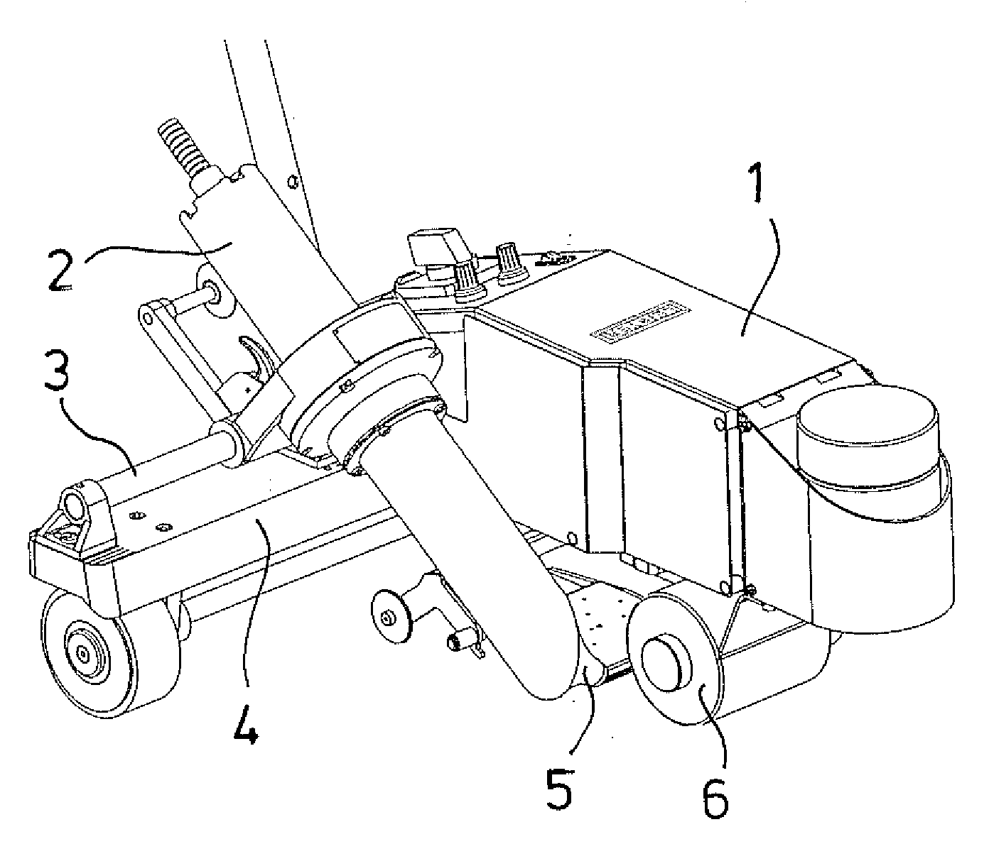
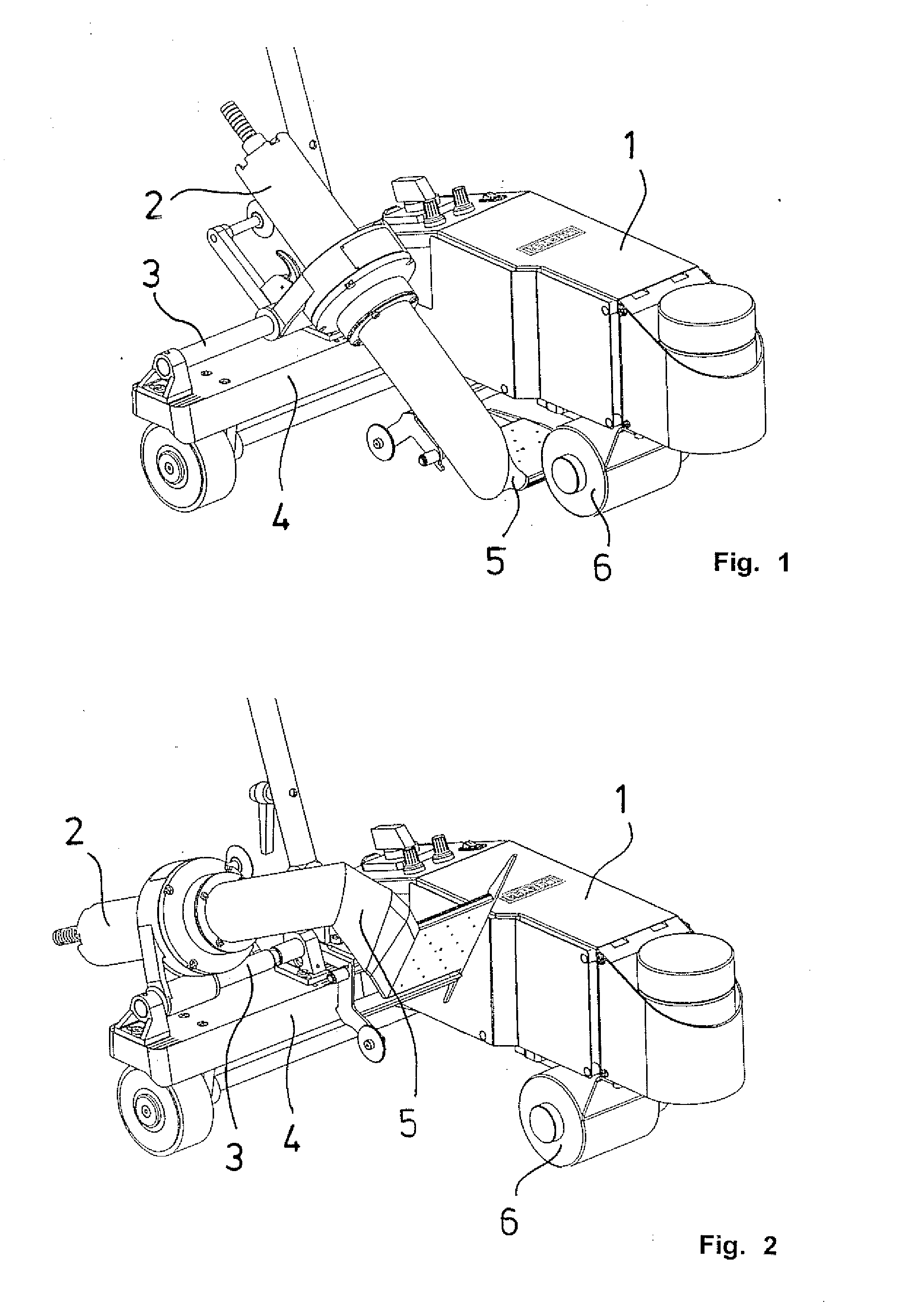
[0011]With the hot air welding nozzle designed as proposed by the invention, and / or the hot air welding device of corresponding design, it is possible to weld webs of sealing material, in particular webs of sealing material made of bitumen, much faster than before, due to the long pre-heating zone.

