
Circulating fluid bed waste incineration boiler with open-type furnace chamber

A circulating fluidized bed and open furnace technology, which is applied to incinerators, combustion methods, combustion types, etc., can solve the problems of needing to shut down the furnace for cleaning, poor fluidization, and large slag discharge port area, so as to prevent coking or slag formation. The effect of slag, simple structure and uniform air distribution

Inactive Publication Date: 2012-01-04
WUXI TAIHU BOILER
View PDF6 Cites 8 Cited by
  • Summary
  • Abstract
  • Description
  • Claims
  • Application Information

AI Technical Summary

Problems solved by technology

[0003] Practice has proved that, whether the above-mentioned air distribution panels are arranged horizontally or inclined, there are elongated substances (such as iron wires, iron nails, etc.) in the garbage that are not easily broken and incombustible The furnace needs to be shut down for cleaning; in addition, due to the large area of ​​the slag outlet, there are still accidents such as easy slagging at the slag outlet during operation despite the adoption of some air distribution measures; The horizontal air distribution plate is better than the horizontal air distribution plate, but the area of ​​the rectangular slag discharge port at the lower part is larger, which is prone to poor fluidization

Method used


Image

  • Circulating fluid bed waste incineration boiler with open-type furnace chamber
  • Circulating fluid bed waste incineration boiler with open-type furnace chamber
  • Circulating fluid bed waste incineration boiler with open-type furnace chamber

Examples


Embodiment Construction

[0015] Its implementation will be further described below in conjunction with the accompanying drawings of the present invention:

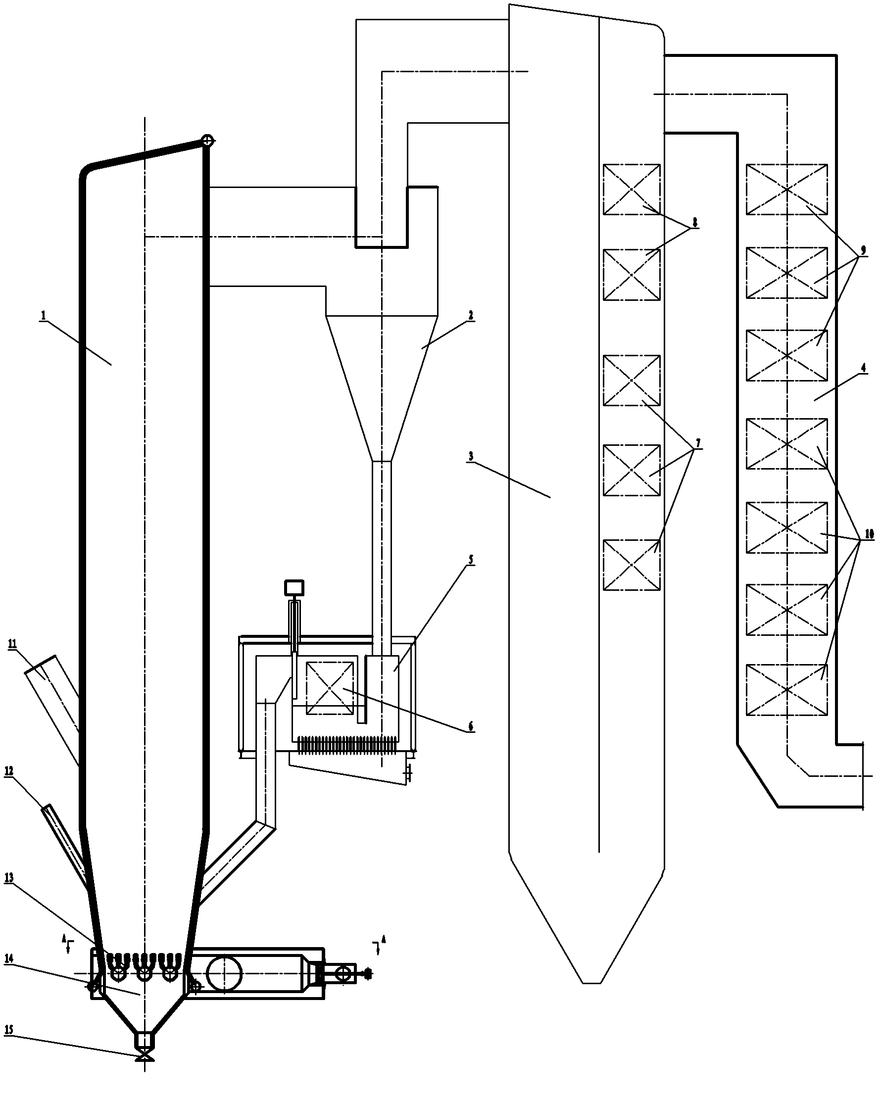
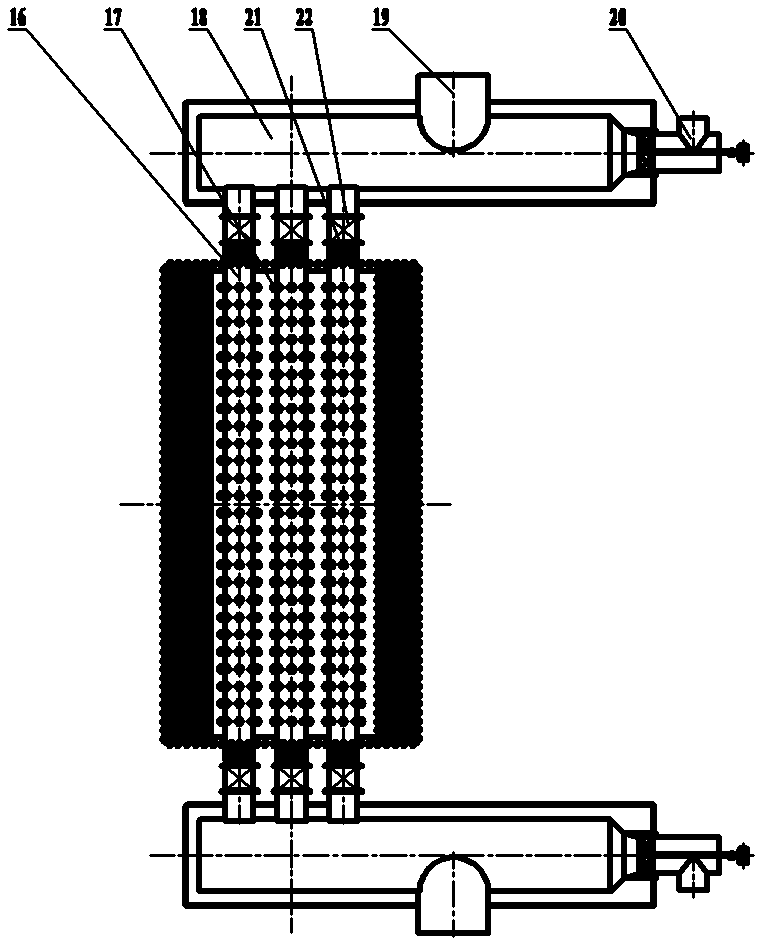
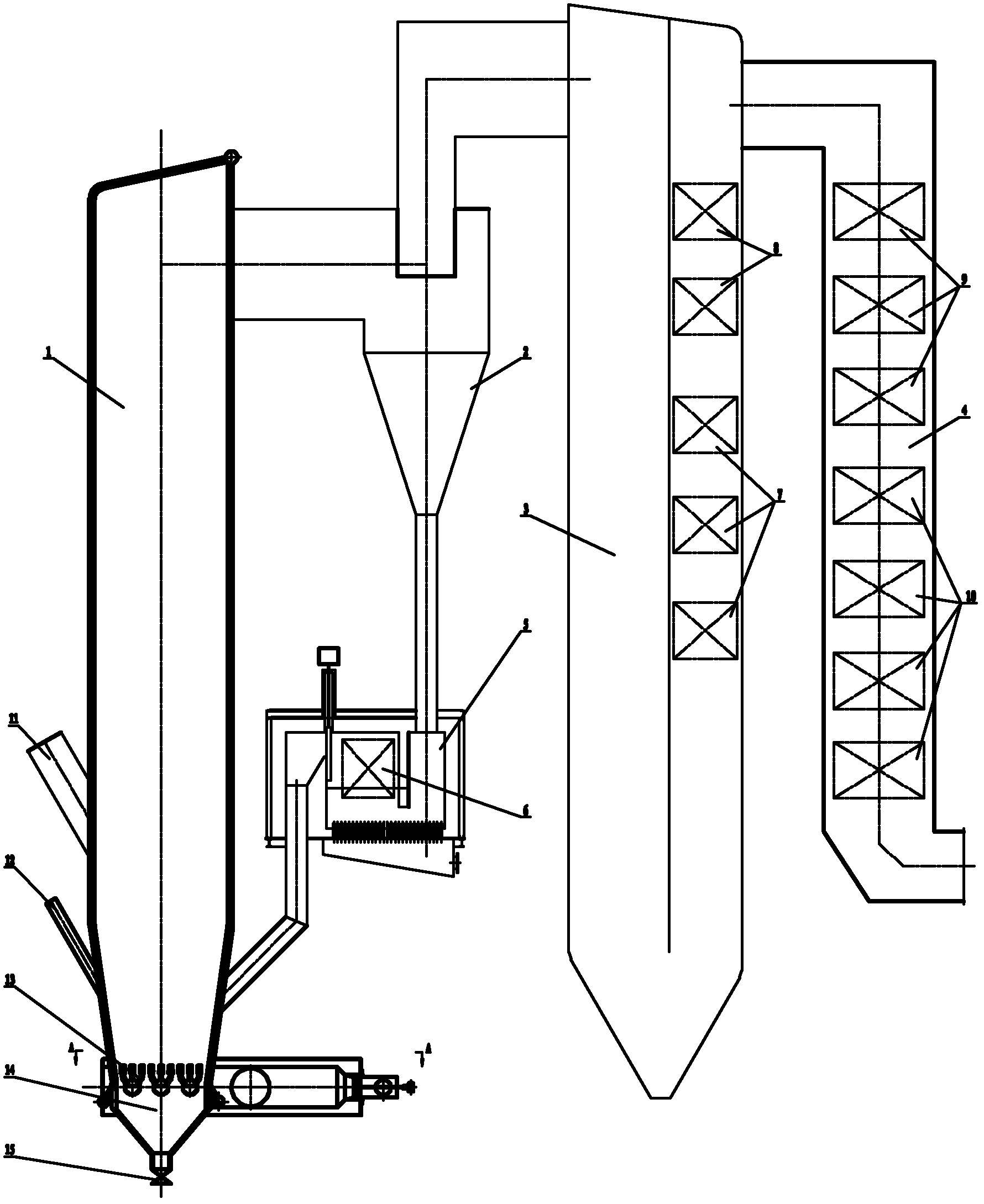
[0016] Such as Figure 1 ~ Figure 2 As shown, it includes open furnace 1, cyclone separator 2, cooling chamber 3, tail convection flue 4, external heat exchanger 5, high temperature superheater 6, low temperature superheater 7, economizer 8, secondary air preheater Heater 9, primary air preheater 10, garbage feed port 11, auxiliary fuel feed port 12, open air distribution plate 13, ash hopper 14, ash valve 15, air distribution pipe 16, exhaust cap 17 , Ignition device 18, primary air inlet 19, ignition oil gun 20, expansion joint 21 and damper 22.

[0017] The present invention mainly consists of sequentially connected open furnace 1, cyclone separator 2, cooling chamber 3 and tail convection flue 4; the lower end of the cyclone separator 2 is connected to an external heat exchanger 5) the external heat exchanger 5 The other end is connected to ...


PUM


Abstract

The invention relates to a circulating fluid bed waste incineration boiler with an open-type furnace chamber. The circulating fluid bed waste incineration boiler comprises the open-type furnace chamber, a cyclone separator, a cooling chamber and a tail convection flue which are connected with one another in turn, wherein the lower end of the cyclone separator is connected with an external heat exchanger, and the other end of the external heat exchanger is connected with the open-type furnace chamber; a high-temperature over-heater is arranged in the external heat exchanger; a plurality of air distribution tubes are arranged on the same horizontal plane equidistantly to form an open-type air distribution plate which is arranged at the bottom of the open-type furnace chamber; an ash hopper is connected below the open-type air distribution plate; a fuel ash valve is arranged below the ash hopper; the open-type air distribution plate separates the upper part of the open-type furnace chamber and the ash hopper; and the open-type air distribution plate consists of the plurality of air distribution tubes. The circulating fluid bed waste incineration boiler can successfully discharge materials which can be easily wound on an air cap, or large-particle or even blocky materials such as iron wires, iron nails and the like in wastes, can uniformly distribute air, is difficult to coke and clinker, and fulfills the aims of prolonging the continuous operation time of the waste incineration boiler and saving energy resources.

Description

technical field [0001] The invention relates to an open furnace circulating fluidized bed garbage incineration boiler, which has the advantage of being able to smoothly discharge iron wires, iron nails and other materials that are easily entangled in the garbage, or materials with large particles or even blocks, and prolong the life of the garbage incineration boiler. Continuous run time. Background technique [0002] At present, most circulating fluidized bed waste incineration boilers use water-cooled air distribution panels similar to coal-fired circulating fluidized bed boilers. Most of them are bent by the furnace membrane water-cooled wall and form a water-cooled air chamber together with the rest of the furnace membrane water-cooled wall. On the top of the water-cooled air chamber is a water-cooled air distribution plate, on which a wind cap for material fluidization is installed; generally, an oil gun ignition burner is installed on the front or rear side of the wat...

Claims


Application Information

Patent Timeline
Patent Type & Authority Applications(China)
IPC IPC(8): F23G5/30F23G5/44
Inventor 李龙孙继常何国光许月琴王啸虎
Owner WUXI TAIHU BOILER
Learn More