Touch input device

a technology of input device and touch, which is applied in the field of touch input device, can solve the problems of limited use of fixed and large-scale panels, complicated and expensive, and the electronic induction method, and achieve the effects of reducing the wide range of use, reducing the cost of use, and reducing the wide range of brushes

Active Publication Date: 2015-03-31
JUNG YOUNG WOO
View PDF14 Cites 3 Cited by
  • Summary
  • Abstract
  • Description
  • Claims
  • Application Information

AI Technical Summary

Benefits of technology

[0013]The present invention is for providing a touch input device which enables a drag task to be performed softly and enables a convenient drawing task.
[0014]Furthermore, the present invention is for providing a touch input device, which is capable of minimizing damage to a surface of a touch panel due to a scratch, etc. and performing a cleaning task on a surface of a touch panel.
[0015]Furthermore, the present invention is for providing a touch input device which has excellent touch performance, can improve durability, and enables a convenient touch task when it is touched at a specific tilt angle.

Problems solved by technology

The ultrasonic wave method touch panel, the light (infrared) sensor method touch panel, the electronic induction method touch panel, etc. are complicated and expensive, and they are not suitable for small-sized touch panel, but are limitedly used in fixed and large-scale panels.
If a user's finger touches the touch panel, however, there are problems in that the touch panel is contaminated or damaged by a sharp nail, etc. and precise manipulation is difficult.
However, the capacitance method touch panel cannot use a resistive film method touch pen and must use a conductive touch pen that is able to be used only in a capacitance method touch panel.
However, malfunction due to noise resulting from environmental factors, for example, moisture in the atmosphere, other external dielectric alien substances and an error due to a temperature drift are likely to occur, and power consumption for a sensing circuit is sharply increased.
As a result, the size of the touch panel input device is inevitably increased.
If a task, such as a drag, is performed in the state in which a touch tip touches or has touched the touch panel, however, there are problems in that the touch panel is inevitably damaged and it is difficult to use the touch panel softly.

Method used


Image

  • Touch input device
  • Touch input device
  • Touch input device

Examples


second embodiment

[0057]FIG. 4 is a cross-sectional view of a touch input device in accordance with the present invention.

[0058]The touch input device in accordance with the second embodiment includes a body 100 grasped by the hand of a user, a brush 110 included in the body 100 and brought in contact with a capacitance method touch panel, and a brush length adjustment unit 120 included in the body 100 and configured to adjust the length of the brush 110 that is drawn.

[0059]The touch input device in accordance with the second embodiment can further include the brush draw unit and the touch pen unit capable of touching a resistive film method touch panel, which have been described in the one embodiment.

[0060]If a contact area where the brush 110 comes into contact with a touch panel can be adjusted, the thickness of a line can be easily adjusted when performing a drawing task and proper handling for the size of a touch panel is possible. That is, in a portable communication device, etc. including a to...

third embodiment

[0068]The touch input device in accordance with the third embodiment includes a body 200 grasped by the hand of a user, a brush 210 disposed at the end of the body 200, disposed in such a way as to be drawn externally, and configured to touch a capacitance method touch panel, and a clicking feeling generation unit 220 configured to generate a feeling of clicking so that a user can check whether the brush 210 has touched a touch panel 60 or not when the brush 210 touches the touch panel 60.

[0069]The touch input device may include only the body 200 configured to have a touch tip included at its end and the clicking feeling generation unit 200 configured to generate a feeling of clicking so that a user can check whether the body has touched the touch panel 60 or not when the body touches the touch panel 60. That is, the touch input device may be implemented without the brush 210. In this case, when a resistive film method touch panel is touched, a feeling of touch can be generated so t...

fourth embodiment

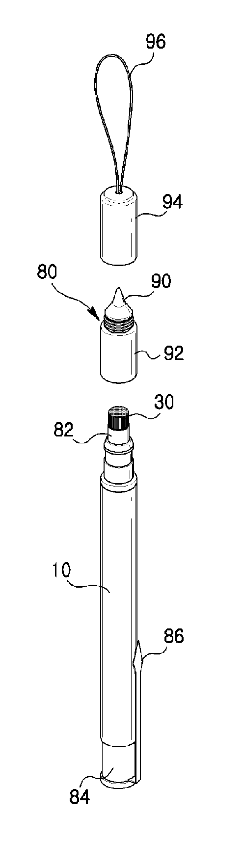
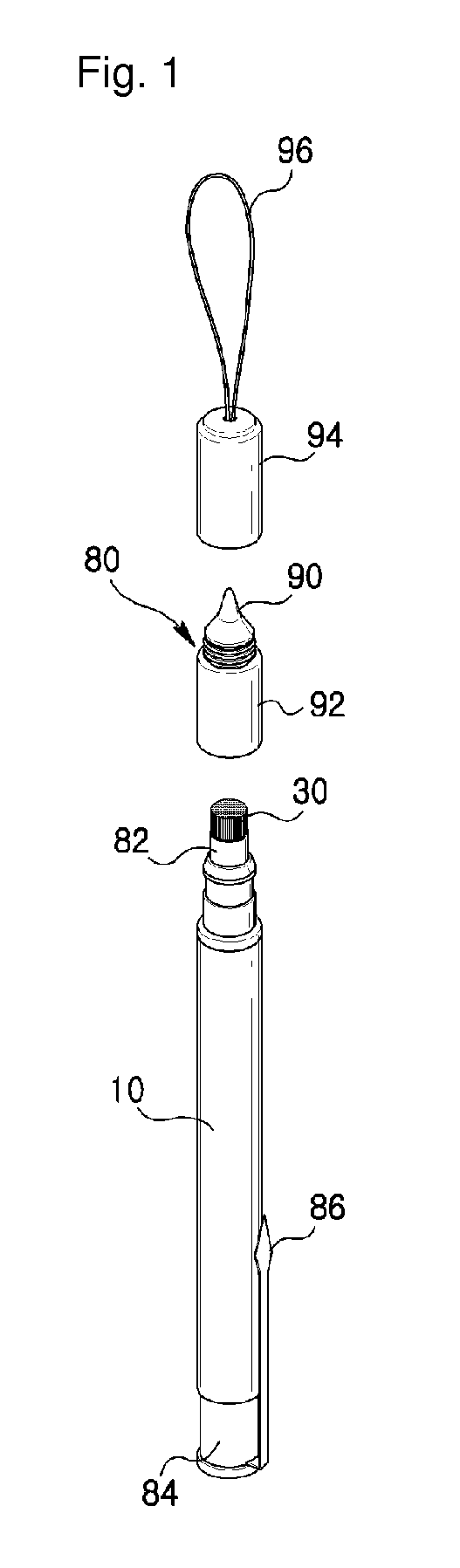
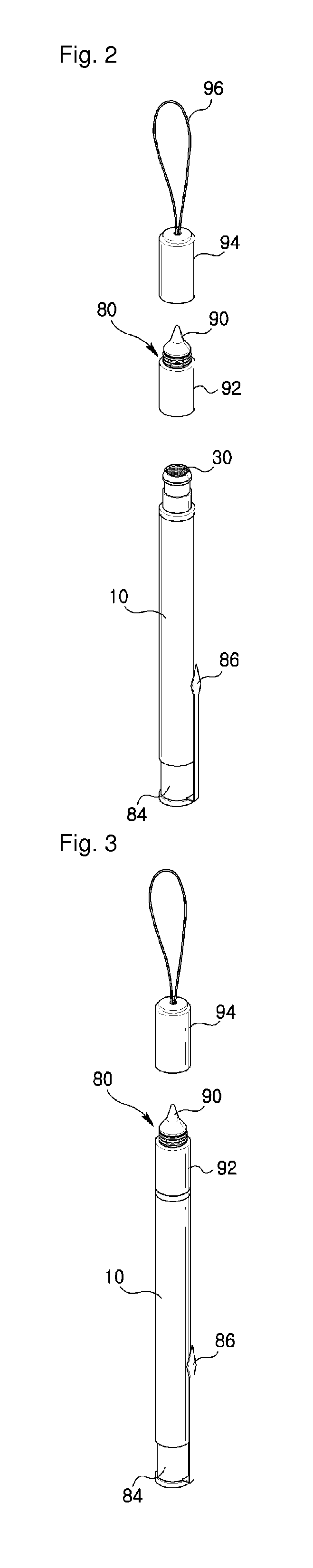
[0081]FIG. 8 is a perspective view of a touch input device in accordance with the present invention.

[0082]The touch input device in accordance with the fourth embodiment includes a body 300, a brush 310 fixed to the end of the body 300 and configured to touch a capacitance method touch panel, and USB memory 320 fixed to the body 300.

[0083]The body 300 can detachably include a cap 330 for protecting the brush 310.

[0084]The body 300 and the brush 310 can include at least one of the elements described in connection with all the embodiments.

[0085]The USB memory 320 includes a housing 322 connected to the body and a connector 324 installed in the housing 322 in such a way as to be drawn therefrom and configured to draw the housing 322 externally when the connector 324 is rotated in one direction.

[0086]The USB memory 320 can include a variety of structures, such as a structure in which the cap is mounted in such a way as to be separated from the connector and a structure in which the conn...


PUM


Abstract

A touch input device comprises: a body made of a conductive material; a brush formed at one end of the body for external extraction, and which is made of a conductive material for touching a capacitive touch panel; and a unit for generating a clicking sensation which is installed within the body to generate a clicking sensation when the touch panel is touched by the brush, thereby enabling a user to sense a click when touching the touch panel, thus improving user convenience, enabling dragging to be smoothly performed, enabling pictures to be easily drawn, minimizing damage such as scratches or the like on the surface of the touch panel, and enabling the surface of the touch panel to be cleaned.

Description

BACKGROUND OF THE INVENTION[0001]The present invention relates to a touch input device for inputting information by touching a touch panel.[0002]A personal computer, a portable transmission device, other personal information processing devices, etc. perform text processing, graphic processing, etc. by using a variety of input devices, such as a keyboard, a mouse, and a digitizer.[0003]The input devices are input device as interfaces according to the expansion of PC use, and the products cannot be handled by using only a keyboard and a mouse. The input devices are being developed owing to the need in which the input devices are simple and less in a mal-operation and anyone can easily perform input and perform text input directly while carrying the input devices.[0004]In particular, there has been known a touch panel which is simple and less in a mal-operation and which enables a user to perform a desired command by only touching a panel so that the user can perform input directly. Th...

Claims


Application Information

Patent Timeline
Patent Type & Authority Patents(United States)
IPC IPC(8): G06F3/033G06F3/0354G06F3/041
CPCG06F3/03545G06F3/039G06F3/044
Inventor JUNG, YOUNG WOO
Owner JUNG YOUNG WOO
Why Eureka
Try Eureka