
Diagnosis assisting apparatus, diagnosis assisting program, and diagnosis assisting method

a technology of diagnostic assisting and diagnostic equipment, applied in the field of diagnostic assisting equipment, computer programs, and methods, can solve problems such as difficult to determine for users unaccustomed to cpr images, and achieve the effect of easy visual recognition and easy comparison

Active Publication Date: 2015-03-31
FUJIFILM CORP
View PDF10 Cites 5 Cited by
  • Summary
  • Abstract
  • Description
  • Claims
  • Application Information

AI Technical Summary

Benefits of technology

[0029]The mark representing the obtained longitudinal section may be anything as long as it is capable of distinguishably indicating the position of the longitudinal section and various types of known marks may be used. That is, the mark may be displayed by giving various transparency values and colors to each pixel constituting the mark. Further the mark may be, for example, a mark that represents only a contour of the longitudinal section. Preferably, the mark is displayed in a manner that allows easy visual recognition of a curved or twisted shape of the longitudinal section. Preferably, the mark is, for example, a curved surface which includes the longitudinal section and has a certain width extending outside of a longitudinal direction of the tubular tissue. Further, it is preferable that the mark is shaded based on an angle of a normal line at each position of the longitudinal section. As used herein, the term “longitudinal section” refers to a surface, which includes a core line of a tubular tissue, along which a curved cutting surface cutting through the tubular tissue projected onto the CPR image in a longitudinal direction passes.
[0036]According to the apparatus, program recorded on a computer readable recording medium, and method of the present invention, a longitudinal section of a tubular tissue is obtained from the CPR image generation means, then a mark representing the obtained longitudinal section, as well as the tubular tissue, are represented in a tubular tissue region, and a pseudo three-dimensional image having the mark is generated based on the volume data and displayed. This allows a doctor to easily understand the position of the tubular tissue represented in the CPR image by observing the mark indicated in the pseudo three-dimensional image.
[0037]If the CPR image generation means is a means that generates a CPR image of a longitudinal section of the tubular tissue region rotated with the core line of the tubular tissue as the axis of the rotation, a pseudo three-dimensional image with a mark rotated according to the rotation of the CPR image is displayed. This allows the position of the longitudinal section to be understood more easily.
[0038]If the mark according to the present invention is a curved surface which includes the longitudinal section and has a certain width extending outside of a longitudinal direction of the tubular tissue, the orientation and position of the longitudinal section represented by the CPR image may be understood from the portion extending outside of the longitudinal direction of the tubular tissue from the longitudinal section, as well as from the longitudinal section, the orientation and position of the longitudinal section may be understood more easily.
[0044]In the present invention, only a portion of the pseudo three-dimensional image representing the tubular tissue within a predetermined distance from the core line is displayed, a desired section of the tubular tissue and mark may be prevented from being hidden by other portions of the tubular tissue in the pseudo three-dimensional image and only the desired section of the tubular tissue and mark may be displayed in a manner that allows easy visual recognition.
[0045]In the present invention, the display control means is a means that causes the pseudo three-dimensional image having the mark and the CPR image to be displayed as a pair of images, the position of the longitudinal section represented by the CPR image and the position of the longitudinal section in the tubular tissue may be compared easily, the longitudinal section of the tubular tissue may be understood more intuitively.

Problems solved by technology

Consequently, it has been difficult for a user unaccustomed to CPR images to determine in which direction the longitudinal section represented by the CPR image is sectioned at each position of a tubular tissue.

Method used


Image

  • Diagnosis assisting apparatus, diagnosis assisting program, and diagnosis assisting method
  • Diagnosis assisting apparatus, diagnosis assisting program, and diagnosis assisting method
  • Diagnosis assisting apparatus, diagnosis assisting program, and diagnosis assisting method

Examples


Embodiment Construction

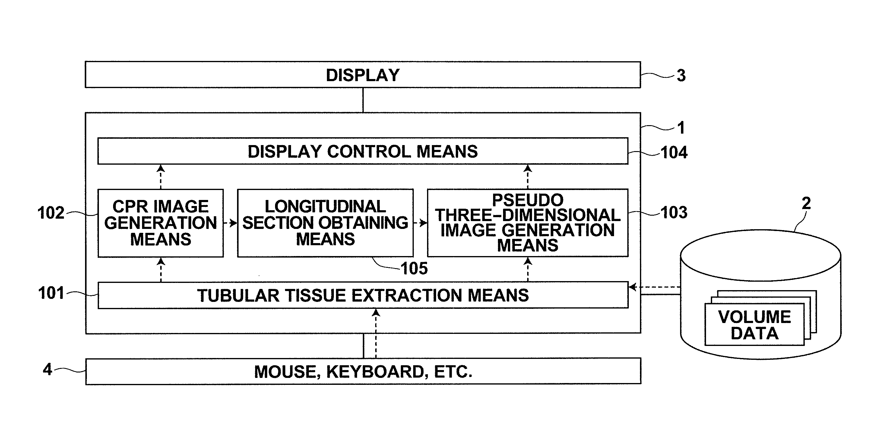
[0054]Hereinafter, embodiments of the diagnosis assisting apparatus, diagnosis assisting method, and diagnosis assisting program of the present invention will be described in detail with reference to the accompanying drawings.

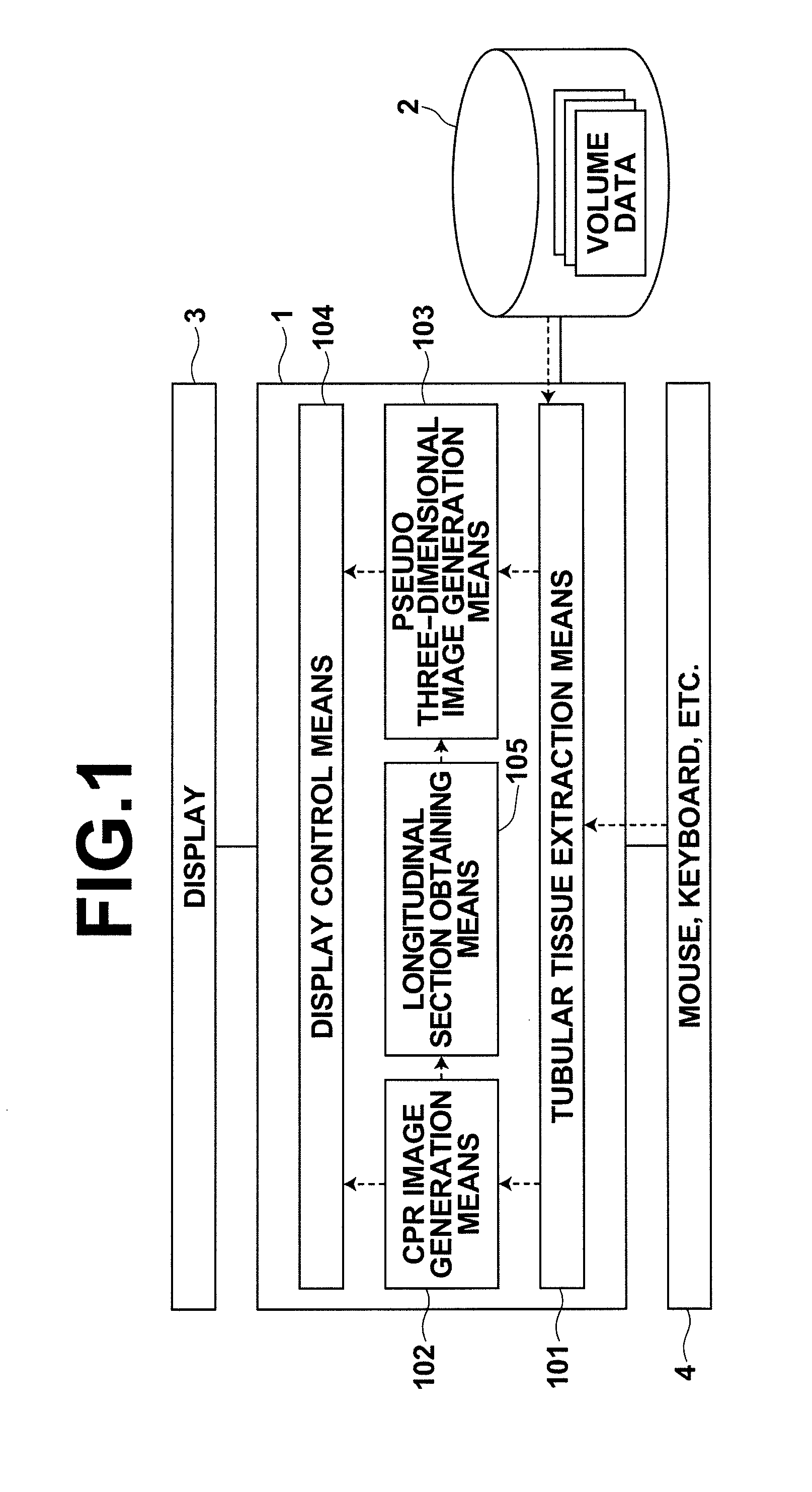
[0055]FIG. 1 illustrates a schematic configuration of a diagnosis assisting apparatus realized by installing a diagnosis assisting program on a workstation used by a doctor. Diagnosis assisting apparatus 1 includes, as a standard configuration, a processor and a memory (which are not shown in FIG. 1) in addition to storage 2, such as a HDD (Hard Disk Drive) or a SSD (Solid State Drive). Further, display 3 and an input device 4, such as a mouse or a keyboard are connected to diagnosis assisting apparatus 1.

[0056]The diagnosis assisting program and data (conversion table to be described later and the like) to be referenced by the program are stored in storage 2 at the time of the installation and loaded in the memory at the time of the activation. The diagnosis a...


PUM


Abstract

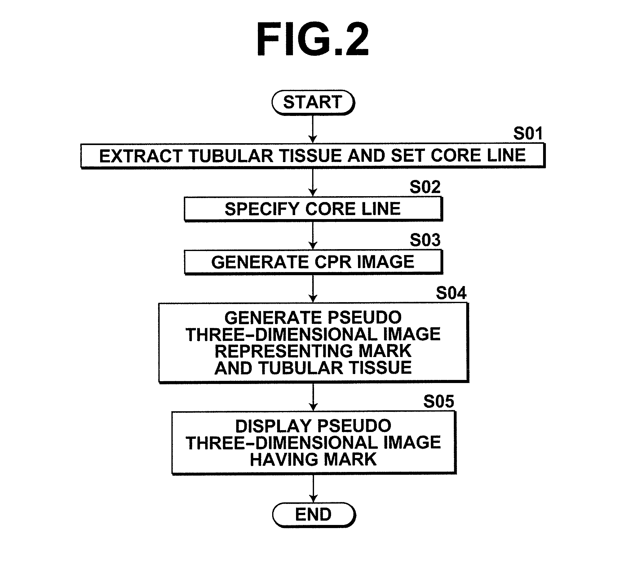
Providing a diagnosis assisting apparatus that allows, in a diagnostic screen of a tubular tissue, easy understanding of the positional relationship between a curved cutting surface represented by a CPR image and the tubular tissue. Extracting a tubular tissue region representing a tubular tissue from volume data obtained by imaging and setting a core line to the tubular tissue, generating a CPR image which includes the core line and a longitudinal section of the tubular tissue region, obtaining the longitudinal section from the CPR image generation means, generating a pseudo three-dimensional image that includes a mark representing the obtained longitudinal section, as well as the tubular tissue in the extracted tubular tissue region based on the volume data, and displaying the pseudo three-dimensional image.

Description

BACKGROUND OF THE INVENTION[0001]1. Field of the Invention[0002]The present invention relates to a diagnosis assisting apparatus, computer program, and method of assisting diagnosis of a tubular tissue through visualization of three-dimensional image data.[0003]2. Description of the Related Art[0004]Technologies for analyzing volume data of an object obtained by CT or the like through CPR method have been developed in order to observe a tubular tissue, such as a blood vessel, intestine, or bronchus as described, for example, in A. Kanitsar et al., “CPR-curved planar reformation”, visualization 2002, VIS2002, IEEE Vol. 1, Issue 1-1 November 2002, pp. 37-44 (Non-patent Document 1). CPR method is a technique in which a curved surface passing the centerline of a tubular tissue is specified based on three-dimensional volume data and the specified curved surface is generated as a two-dimensional image. This allows a cross-section of the tubular tissue in the longitudinal direction to be d...

Claims


Application Information

Patent Timeline
Patent Type & Authority Patents(United States)
IPC IPC(8): G06T15/00G06T15/08G06T19/00
CPCG06T19/00G06T15/08G06T2215/06
Inventor MASUMOTO, JUN
Owner FUJIFILM CORP
Learn More