Battery connecting assembly

a battery connection and assembly technology, applied in the direction of battery connection, coupling device connection, cell components, etc., can solve the problems of increased cost, increased size of the mold to form the battery connection plate, and complicated operation

Inactive Publication Date: 2015-04-07
AUTONETWORKS TECH LTD +2
View PDF12 Cites 5 Cited by
  • Summary
  • Abstract
  • Description
  • Claims
  • Application Information

AI Technical Summary

Benefits of technology

[0014]In other words, in the present invention, mounting the power line on the wire mounting portion of the connecting unit can form the connecting units in a single unit. Then, the connecting units formed in a single unit are connected to the electric cell group to connect the battery connecting assembly to the electric cell group. Thus, it is possible to simplify connection work.
[0015]When the spacing between the electrode terminals of the adjacent electric cells is varied, or when the electric cells expand and contract in the direction of arranging the cells to increase a variation in the spacing between the electrode terminals, misalignment sometimes occurs between the connecting member and the electrode terminal. However, in the present invention, since the connecting units are coupled using the power line mounted on the wire mounting portion, the connecting units are movable along the power line. Consequently, according to the present invention, it is possible to compensate the misalignment between the connecting member and the electrode terminal, and it is possible to facilitate the connection work of the battery connecting assembly.
[0016]Moreover, in the present invention, since the connecting units connect the electrode terminals to each other, the number of the connecting units maybe changed in the case of changing the number of the electric cells to be connected. Namely, in the present invention, even though the number of the electric cells to be connected is increased, it is unnecessary to prepare molds whenever the number is increased. Consequently, according to the present invention, it is possible to reduce manufacturing costs.
[0017]According to the present invention, it is possible to provide a battery connecting assembly configured to simplify connection work and compensate the misalignment between a connecting member and an electrode terminal to facilitate connection work while reducing manufacturing costs.

Problems solved by technology

In assembling the battery module in the configuration above, since it is necessary to connect the electrode terminals at a plurality of locations using the connecting member, a complicated operation is necessary to repeat an operation of connecting the connecting member between the electrode terminals.
However, in the case of using a battery connection plate having connecting members integrally molded, a mold to form the battery connection plate is increased in size and the costs are increased when the number of electric cells becomes large.
Moreover, in the case of changing the number of electric cells, it is necessary that a different mold having a length according to the number of electric cells be newly prepared to mold a battery connection plate having a different length, causing a cost increase in forming a mold or the like.
Therefore, there is a challenge in that manufacturing costs are reduced.
However, when the spacing between the electrode terminals of the adjacent electric cells is varied, misalignment sometimes occurs between the connecting member and the electrode terminal when mounting the connection plate in the configuration above.
Particularly in the case of mounting a connection plate having connecting units firmly coupled to each other on an electric cell group, it is difficult to compensate the misalignment between the connecting member and the electrode terminal to cause a possibility to hamper smooth mounting work.
Moreover, when electric cells forming a battery module expand and contract in the direction of arranging the cells to increase a variation in the spacing between the electrode terminals, it is likely to cause a difficulty to compensate the misalignment in the connection plate in the configuration above.

Method used


Image

  • Battery connecting assembly
  • Battery connecting assembly
  • Battery connecting assembly

Examples


first embodiment

[0050]the present invention will be described with reference to FIGS. 1 to 5.

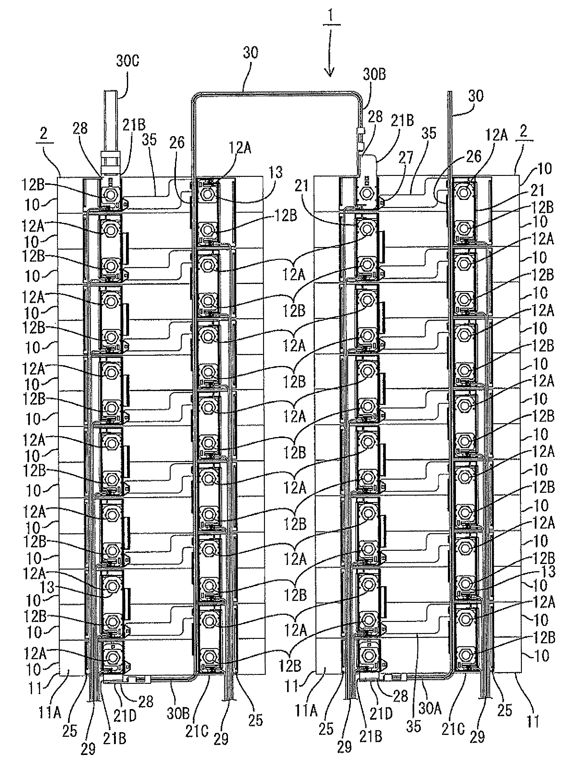
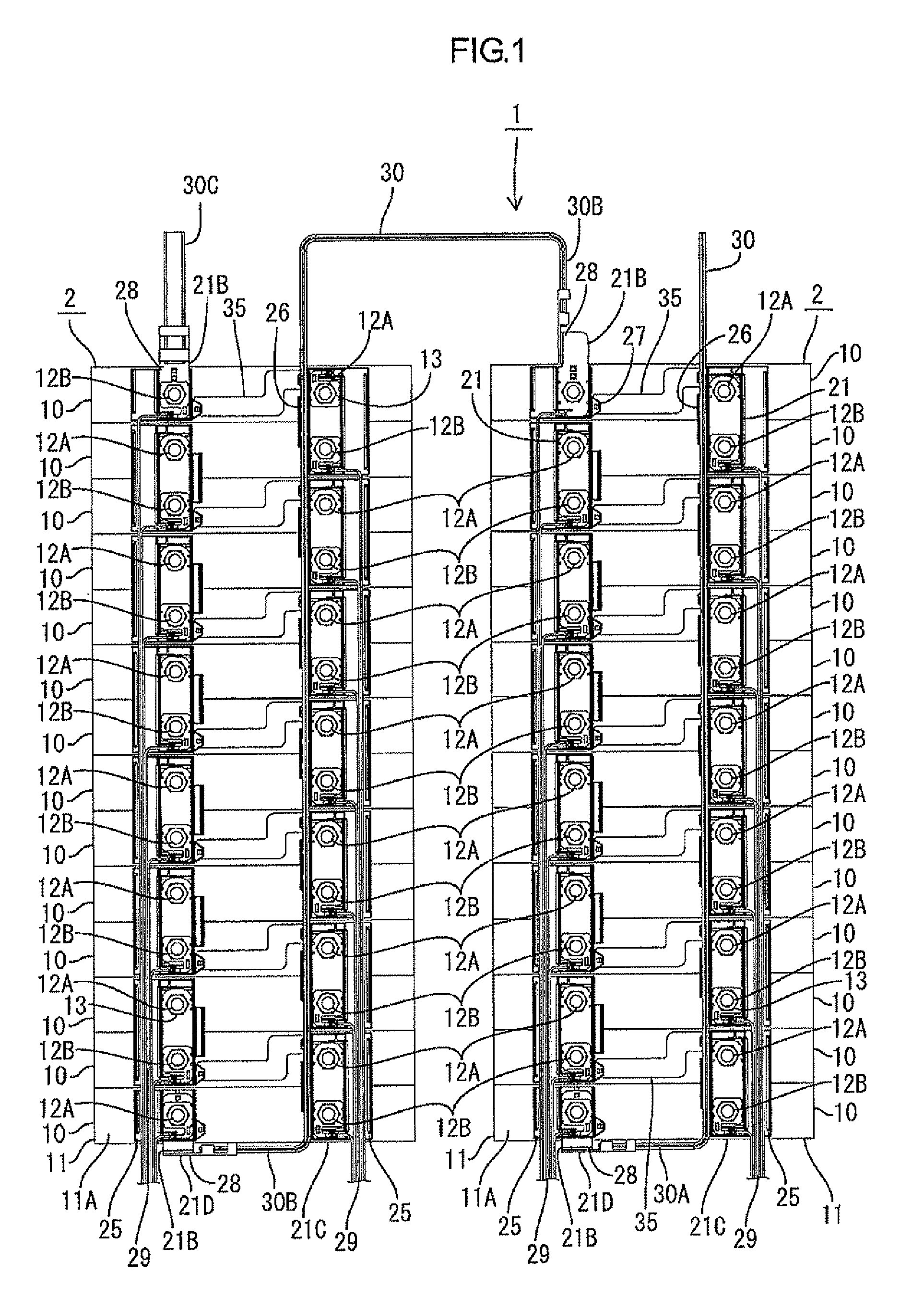
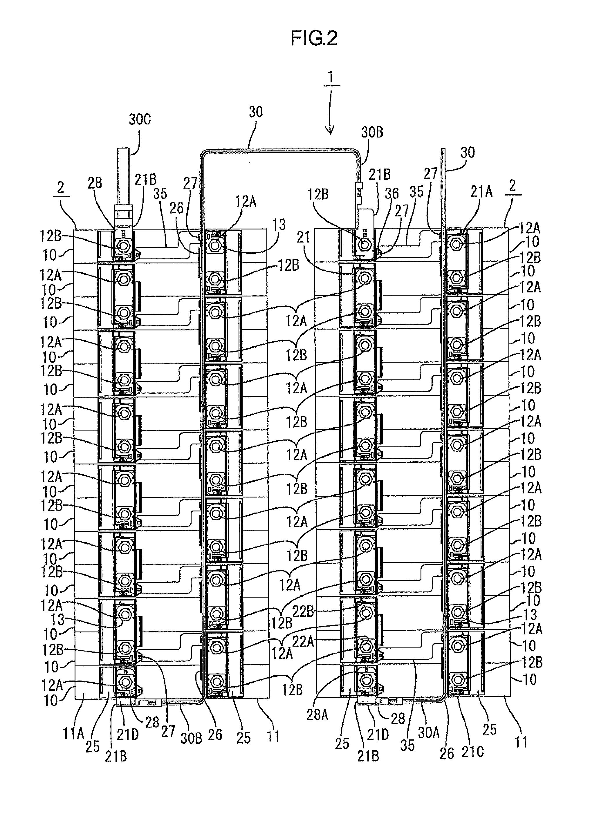
[0051]A battery module 1 according to the present embodiment is used for the driving source of an electric car or a hybrid car, for example, including a battery connecting assembly 20 that connects electric cell groups 2 in two lines as depicted in FIG. 1. In the following, the description will be given in which based on the lateral direction in FIG. 1, the upper side in FIG. 1 is the forward side and the lower side is the rear side.

[0052]The electric cell group 2 includes a plurality of electric cells 10 (fourteen electric cells 10) arranged in a column from the front side to the rear side. The electric cells 10 forming the electric cell group 2 include a body 11 that accommodates a power generating element, not depicted, thereinside and bolt-like electrode terminals 12A and 12B (in the drawing, a positive electrode is the electrode terminal 12A and a negative electrode is the electrode terminal 12B) protr...


PUM

PropertyMeasurementUnit
thicknessaaaaaaaaaa
voltageaaaaaaaaaa
sizeaaaaaaaaaa

Abstract

A battery connecting assembly includes: a power line having the outer circumferential portion of a conductor covered with an insulating resin and connected to electrode terminals; and a connecting units including: a connecting member that connects the adjacent electrode terminals to each other; and a wire mounting portion that mounts the power line thereon along the direction of arranging electric cells. The connecting units are coupled to each by mounting the power line on the wire mounting portion of the connecting units.

Description

TECHNICAL FIELD[0001]The present invention relates to a battery connecting assembly.BACKGROUND ART[0002]A battery module for an electric car and a hybrid car includes an electric cell group in which a plurality of electric cells having positive and negative electrode terminals is arranged. The electric cells forming the electric cell group are connected in series or in parallel in which the electrode terminals of the adjacent electric cells are connected using a connecting member such as a bus bar (see Patent Document 1).[0003]Patent Document 1: Japanese Unexamined Patent Publication No. 11-67184[0004]In assembling the battery module in the configuration above, since it is necessary to connect the electrode terminals at a plurality of locations using the connecting member, a complicated operation is necessary to repeat an operation of connecting the connecting member between the electrode terminals.[0005]Therefore, it is considered to form a battery connection plate in which a plura...

Claims


Application Information

Patent Timeline
Patent Type & Authority Patents(United States)
IPC IPC(8): H01R24/00H01R33/00B60L11/18H01M10/48H01M50/209H01M50/278H01M50/516H01M50/522
CPCH01M2/202H01M2/206B60L11/1877H01M2/1077H01M10/482H01M2220/20B60L50/66Y02T10/70Y02E60/10H01M50/278H01M50/209H01M50/522H01M50/516
Inventor OKAMOTO, RYOYATAKASE, SHINICHIHIRAI, HIROKIKASUGAI, MASAKUNI
Owner AUTONETWORKS TECH LTD
Why Eureka
Try Eureka