Shield cover, shield case, and circuit board module

a shield cover and shield case technology, applied in the direction of coupling device details, rack/frame construction, coupling device connection, etc., can solve the problems of increasing costs, and achieve the effect of reducing costs, reducing costs, and simplifying the connection work of the contact portion

Inactive Publication Date: 2013-08-06
HOSIDEN CORP
View PDF20 Cites 3 Cited by
  • Summary
  • Abstract
  • Description
  • Claims
  • Application Information

AI Technical Summary

Benefits of technology

[0008]In view of the above circumstances, the present invention provides a shield caver, a shield case, and a circuit board module that can obviate soldering work and screw clamp work, and that are reduced in height.
[0010]In this aspect of the invention, the contact portion is elastically contactable with the first lateral surface of the metal shell, obviating soldering or screwing work for connecting the contact portion to the metal shell. Consequently, the connection work of the contact portion becomes remarkably simplified, leading to reduced cost. Moreover, the contact portion, elastically contactable with the first lateral surface of the metal shell, a top plate of the shield cover can be disposed close to the connector. Consequently, the shield cover can be minimized in height dimension.
[0011]The metal shell may further include a second lateral surface that is opposite from the first lateral surface. The shield cover may have a pair of the contact portions, which may be elastically contactable with the first and second lateral surfaces of the metal shell from opposite sides of the connector. In this case, since the contact portions elastically contact with the lateral surfaces of the metal shell from opposite sides of the connector to sandwich the connector, the electric connection of the contact portions with the lateral surfaces of the metal shell of the connector is improved in stability and reliability.

Problems solved by technology

However, in order to connect the contact portion of the shield case to the top surface of the metal shell of the connector by soldering or by a screw, it is inevitable to do bothersome work of soldering or screwing, which leads to increased costs.

Method used


Image

  • Shield cover, shield case, and circuit board module
  • Shield cover, shield case, and circuit board module
  • Shield cover, shield case, and circuit board module

Examples


Embodiment Construction

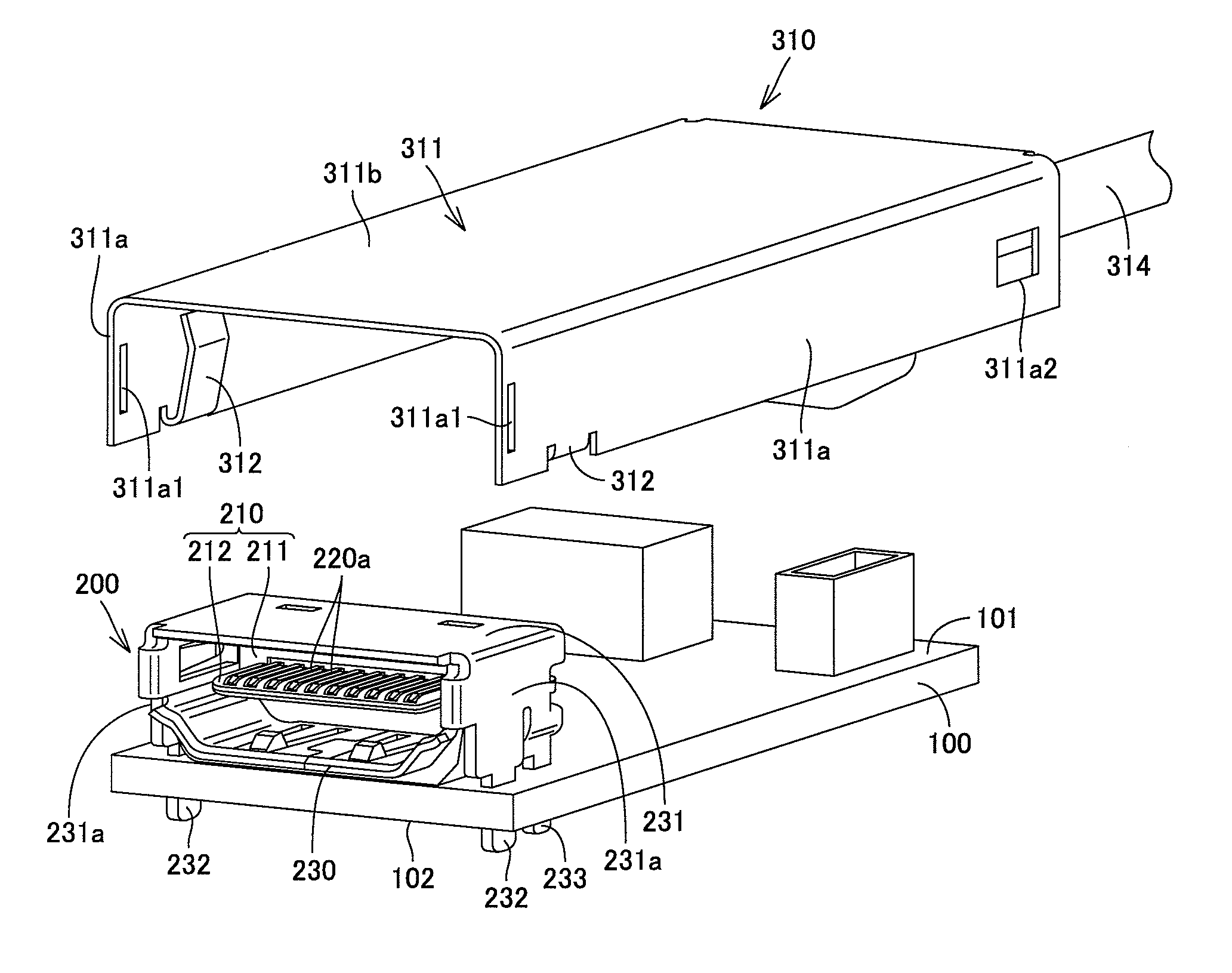
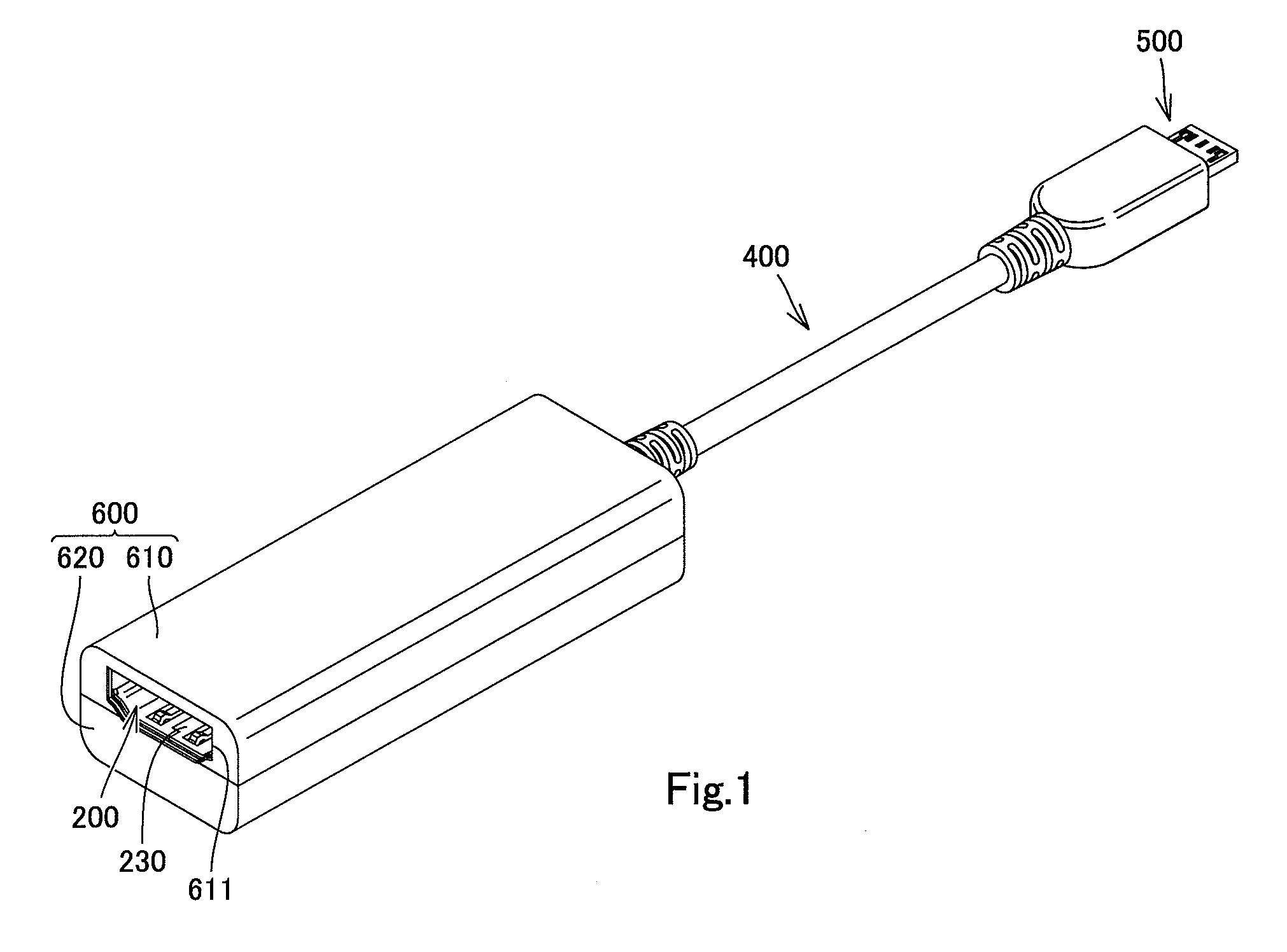
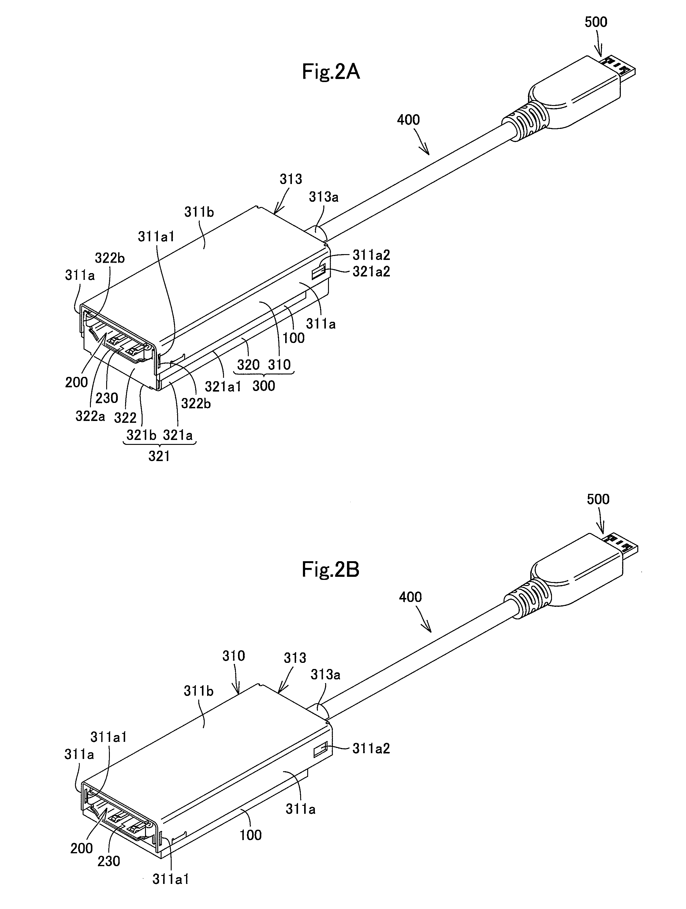
[0027]Hereinafter, a circuit board module according to an embodiment of the present invention will be described with reference to FIGS. 1 to 4. The circuit board module shown in FIGS. 1 to 4 is a relay device for inputting and outputting digital signals at a high transmission frequency in the range of several tens of MHz to several GHz). The circuit board module is proof against electromagnetic interference (EMI). This circuit board module includes a circuit board 100, a female connector 200, a shield case 300, a cable 400, a male connector 500 and a resin case 600. These respective components will be described in detail below.

[0028]The circuit board 100 is a well-known printed circuit board having a first surface 101 and a second surface 102, as shown in FIGS. 2A to 4. On the first surface 101 of the circuit board 100 is mounted the female connector 200. Although not shown, the first surface 101 is further provided with a plurality of input / output terminals, conductive lines to tra...


PUM


Abstract

The invention provides a shield cover adapted to cover at least a first electronic component mounted on a first surface of a circuit board. The first electronic component has a metal shell or has a ground / earth terminal on a lateral surface thereof. The shield cover has a contact portion being elastically contactable with a lateral surface of the metal shell or the ground / earth terminal of the first electronic component.

Description

[0001]The present application claims priority under 35 U.S.C. §119 of Japanese Patent Application No. 2009-235899 filed on Oct. 13, 2009, the disclosure of which is expressly incorporated by reference herein in its entity.BACKGROUND OF THE INVENTION[0002]1. Technical Field[0003]The present invention relates to a shield cover capable of covering at least a first electronic component mounted on a first surface of a circuit board. The invention also relates a shield case and a circuit board module provided with the shield cover.[0004]2. Background Art[0005]A conventional shield case as disclosed in Japanese Unexamined Patent Publication No. 2009-123500 covers a whole circuit board with a connecter (electronic component) mounted thereon in order to enhance electromagnetic interference (EMI) characteristics. This shield case has a contact portion to be connected to the top surface of a metal shell of the connector by soldering or by screwing.CITATION LIST[0006]Patent Literature 1: Japane...

Claims


Application Information

Patent Timeline
Patent Type & Authority Patents(United States)
IPC IPC(8): H05K9/00
CPCH01R13/6658H01R13/65802H01R13/6582
Inventor NAGATA, TAKAYUKIOHTSUJI, TAKAHISA
Owner HOSIDEN CORP
Why Eureka
Try Eureka