Clamping pliers

a technology of pliers and pliers, which is applied in the direction of pliers, manufacturing tools, etc., can solve the problems of unusable locking mechanisms of known pliers and the operator having to use both hands to operate the pliers

Inactive Publication Date: 2015-04-14
PRIVATE BRAND TOOLS AUSTRALIA
View PDF9 Cites 6 Cited by
  • Summary
  • Abstract
  • Description
  • Claims
  • Application Information

AI Technical Summary

Benefits of technology

[0017]Each handle may be of any suitable size, shape and construction and can be made of any suitable material or materials. Typically, the handles will be made of metal or plastics material, but preferably plastics material. Preferably, the handles are able to slightly flex toward one another within the common plane whilst clamping the jaws to the fluid line, so that the locking mechanism can lock the jaws in a tighter clamping position and provide a tighter clamping action.
[0032]The locking mechanism may further comprise at least one travel stop for preventing the retainer from pivoting beyond a certain point relative to the second shank. The travel stop may be of any suitable size, shape and construction and may be formed of any suitable material or materials. Typically, the travel stop will be made of metal and / or plastics material, but preferably plastics material. Preferably, the travel stop is of unitary construction with the first and / or second shank. The first shank or first jaw may prevent the retainer from pivoting beyond the non-locking position. The second shank may prevent the retainer from pivoting beyond the locking position.

Problems solved by technology

One disadvantage of known pinch-off pliers is that an operator must use both hands when operating the pliers.
In particular, the locking mechanism of known pliers are not user friendly and require two hands to position.

Method used


Image

  • Clamping pliers
  • Clamping pliers
  • Clamping pliers

Examples


Embodiment Construction

[0050]In the figures, like reference numerals refer to like features.

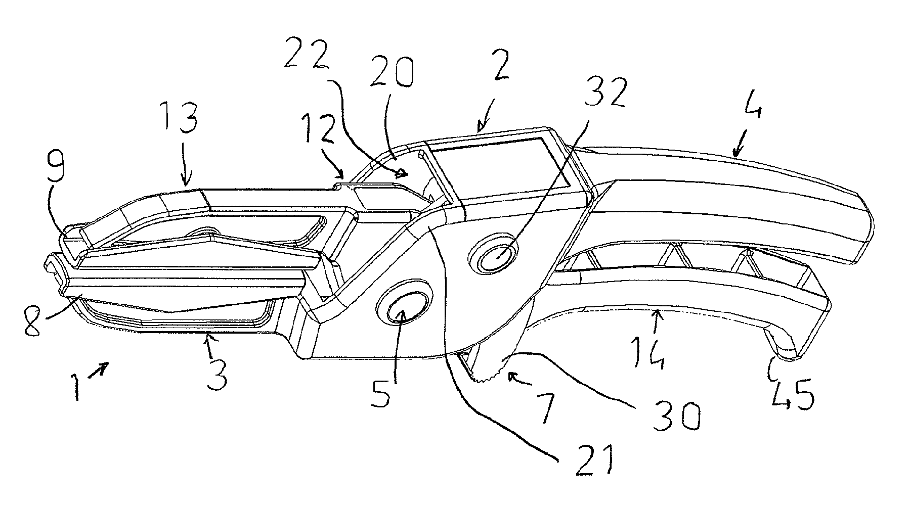
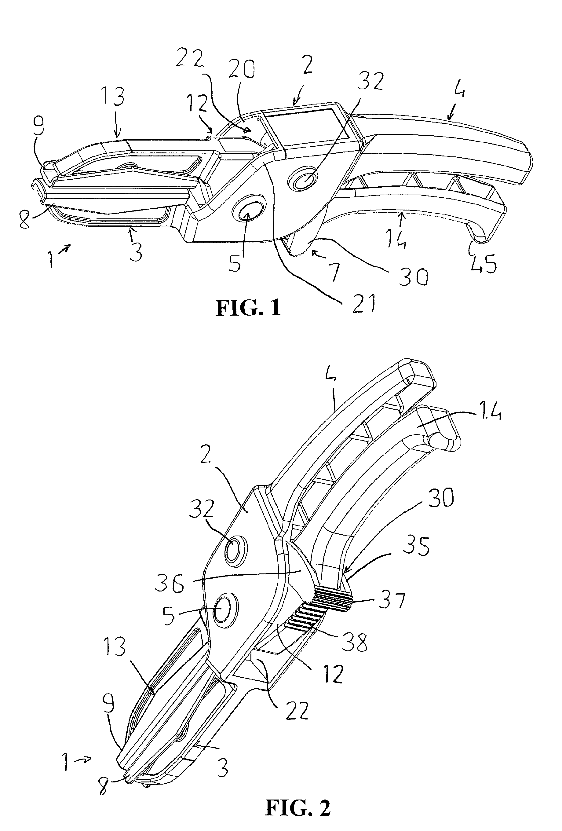
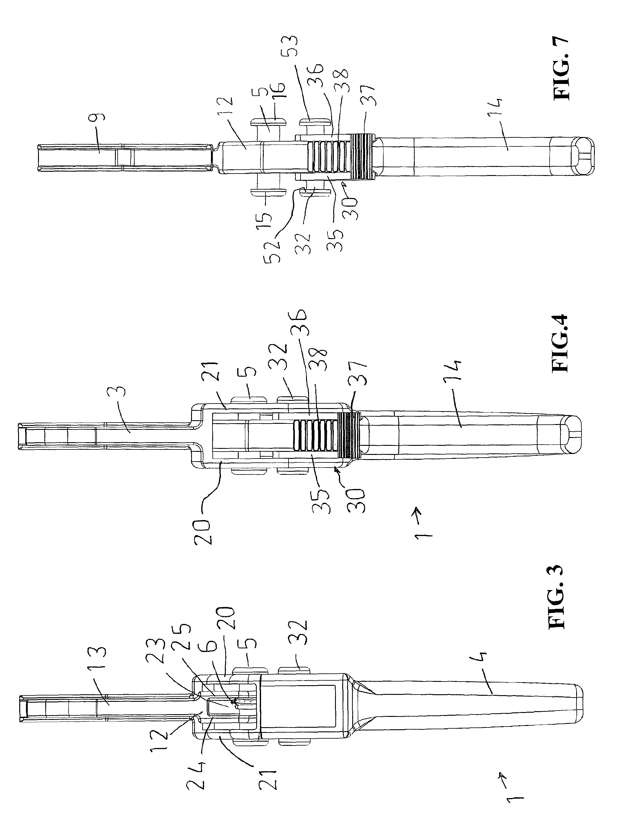
[0051]The figures show clamping pliers 1 for pinching closed a fluid line 100 (eg. a rubber radiator hose as seen in FIGS. 10 and 11). The clamping pliers 1 comprise a first shank 2, a first jaw 3, a first handle 4, a second shank 12, a second jaw 13, a second handle 14, a pivot 5, a biasing mechanism 6 (see FIG. 3), a locking mechanism 7 (see FIGS. 2 and 8) and jaw plates 8, 9.

[0052]The first shank 2, first jaw 3 and first handle 4 are of unitary construction and are made of moulded plastics material. Likewise, the second shank 12, second jaw 13 and second handle 14 are of unitary construction and are made of moulded plastics material. The shanks 2, 12, jaws 3, 13 and handles 4, 14 extend within a common plane.

[0053]The pivot 5 is in the form of a pivot pin 5 and connects the first and second shanks 2, 12 (much like a scissor arrangement) such that the first and second jaws 3, 13 are opposed to one another and mov...


PUM


Abstract

Fluid line clamping pliers include shanks, jaws, handles, a pivot connecting the shanks such that first and second jaws are opposed to one another and movable using first and second handles within a common plane between a clamping position and a non-clamping position. The pliers include a biasing mechanism, a locking mechanism, and a retainer return mechanism. A retainer is adapted to be pivoted to a locking position using an index finger of an operator of the clamping pliers while the operator's other fingers grasp the handles of the clamping pliers, and the retainer return mechanism is adapted to move the retainer from a locking position to a non-locking position when the operator squeezes the handles towards one another while the jaws are in a clamping position.

Description

TECHNICAL FIELD[0001]The present invention concerns clamping pliers for pinching closed a fluid line. In particular, the invention concerns clamping pliers having a locking mechanism that can be used to pinch closed a fluid line using a single hand.BACKGROUND OF THE INVENTION[0002]In the automotive industry, fluid lines in the form of flexible pipes or hoses are used to convey fluids such as air, coolant, oil and fuel from one vehicle component to another. During servicing of a vehicle it may be necessary to disconnect or cut a fluid line, in which case fluid could leak from an opening in the fluid line unless manually sealed by a technician.[0003]Depending on the nature of the fluid line and the fluid leaking therefrom, technicians may simply allow the fluid to drain from within the fluid line into a collection container (eg. pan), or temporarily seal the opening in the fluid line by way of a closure such as a plug, or temporarily close off a flexible fluid line by way of a hose cl...

Claims


Application Information

Patent Timeline
Patent Type & Authority Patents(United States)
IPC IPC(8): B25B7/14B25B7/02
CPCB25B7/02B25B7/14
Inventor MITCHELL, DAVID
Owner PRIVATE BRAND TOOLS AUSTRALIA
Why Eureka
Try Eureka