Rotary compressor having discharge groove to communicate compression chamber with discharge port near vane groove

a rotary compressor and discharge port technology, applied in the direction of rotary/oscillating piston pump components, machines/engines, liquid fuel engines, etc., can solve the problems of cop worsening and the compression effect reducing

Active Publication Date: 2015-04-14
FUJITSU GENERAL LTD
View PDF6 Cites 5 Cited by
  • Summary
  • Abstract
  • Description
  • Claims
  • Application Information

AI Technical Summary

Benefits of technology

[0011]The present invention has been made considering the above-stated matters and aims to decrease the over compression loss and improve the compression effect so as to obtain a rotary compressor with better COP.

Problems solved by technology

However, according to the conventional art disclosed in Japanese Patent Application Laid-open No. 05-133363, since the discharge port is located completely inside the compression chamber of the cylinder and a discharge notch is not provided in the compression chamber of the cylinder, although it is possible to decrease re-expansion loss, after the roller passes through the discharge port, refrigerant gas which is not discharged is compressed resulting in over compression loss in a space surrounded by the inner wall of the cylinder, the roller, and the vane, and the high pressure refrigerant gas returns to the suction chamber side of low pressure, causing decrease in compression effect and worsening of COP, which must be the problem.

Method used


Image

  • Rotary compressor having discharge groove to communicate compression chamber with discharge port near vane groove
  • Rotary compressor having discharge groove to communicate compression chamber with discharge port near vane groove
  • Rotary compressor having discharge groove to communicate compression chamber with discharge port near vane groove

Examples


first embodiment

[0023

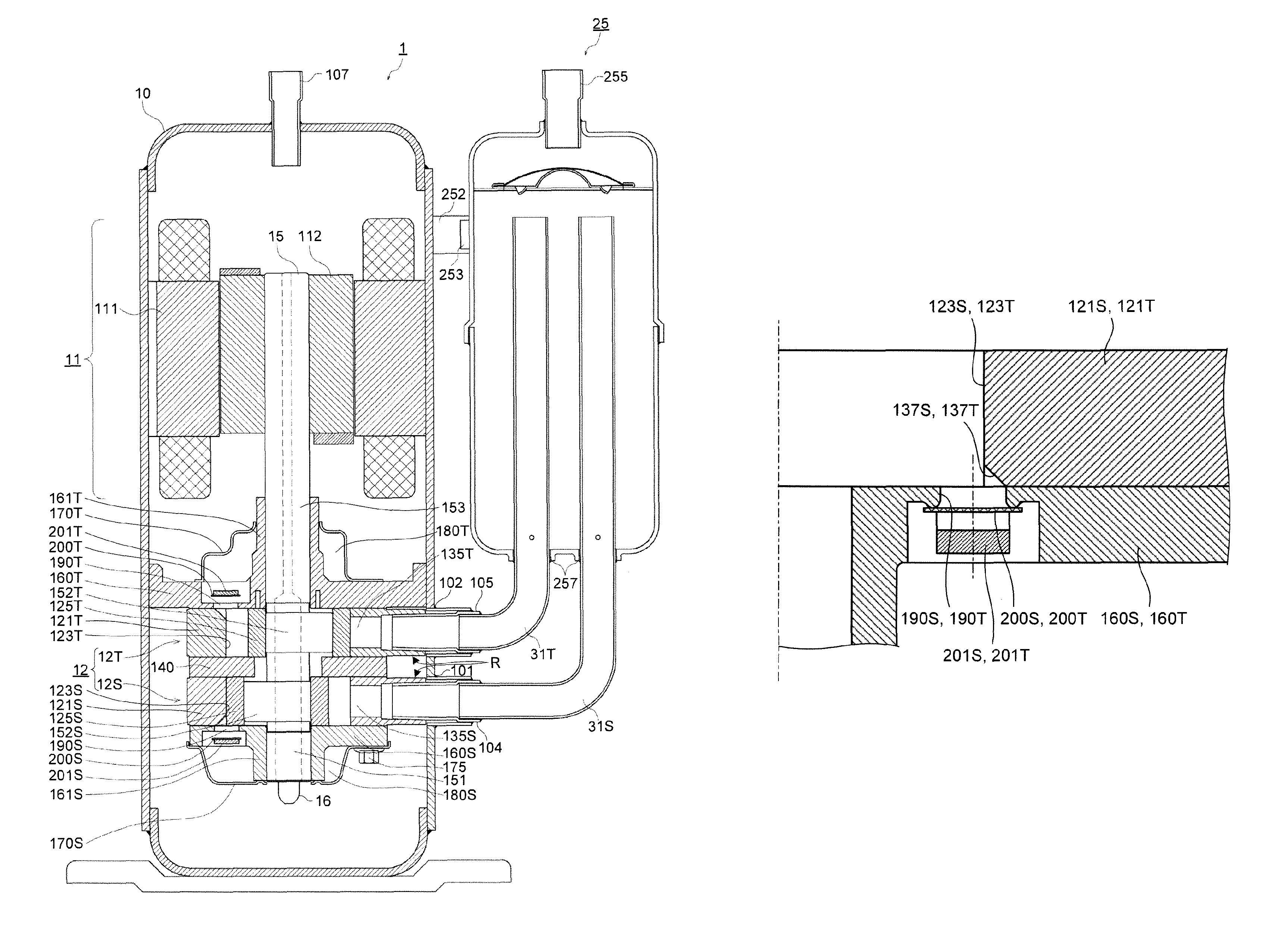
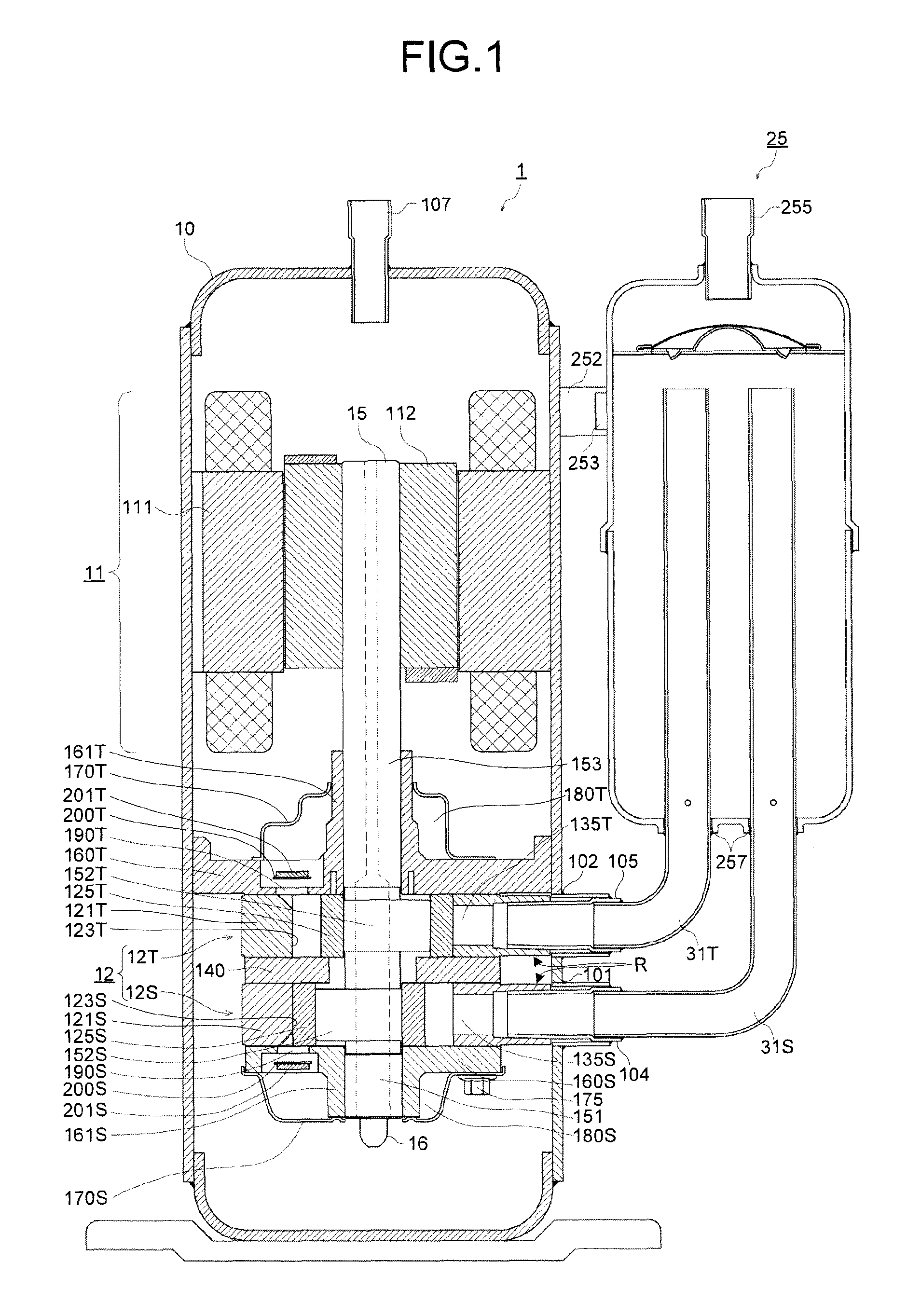
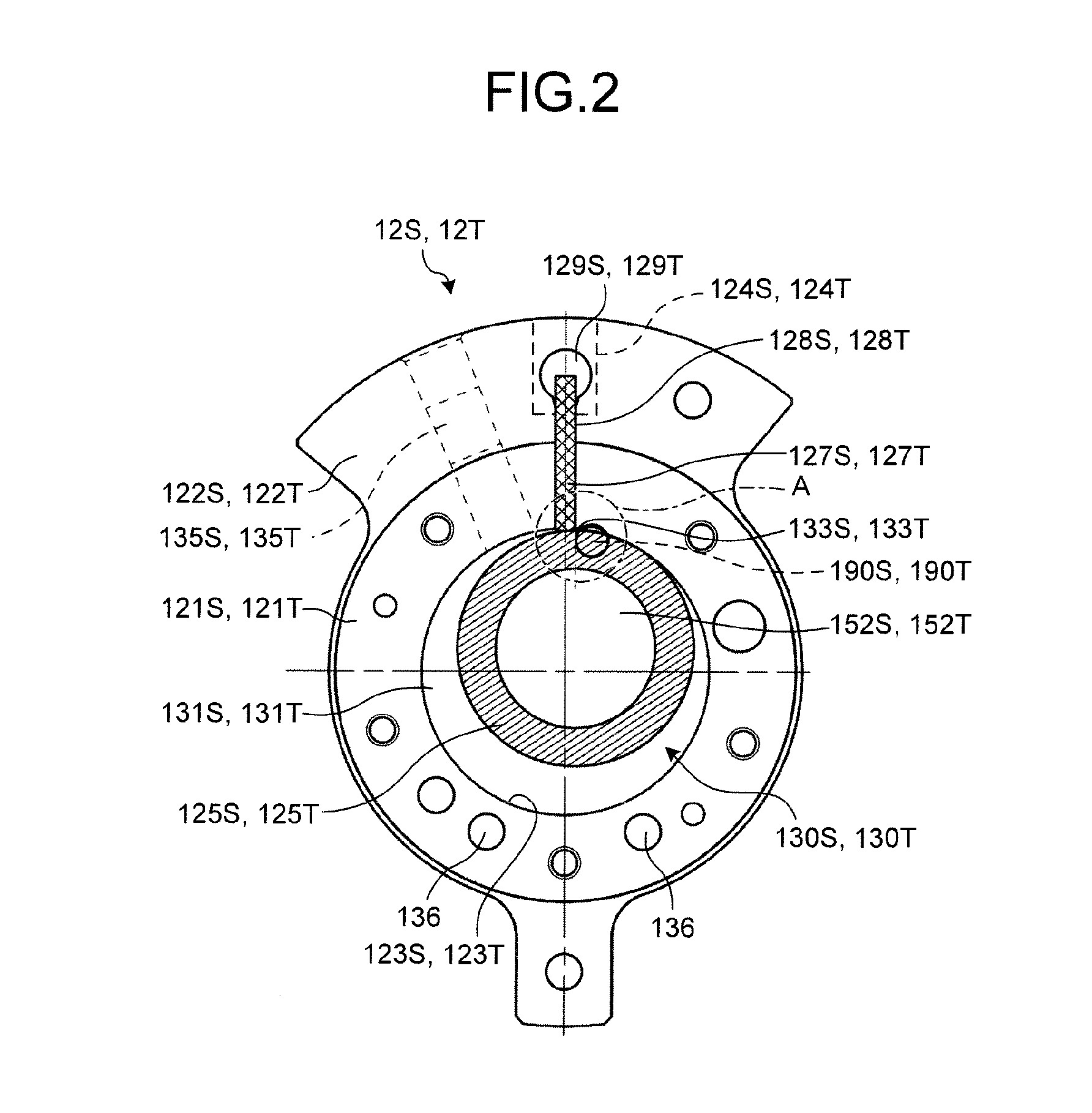
[0024]FIG. 1 is a longitudinal sectional view illustrating an embodiment of the rotary compressor according to the present invention, and FIG. 2 is a plan view illustrating the first and second compression units of a first embodiment.

[0025]As illustrated in FIG. 1, a rotary compressor 1 of the embodiment includes a compression unit 12 arranged at the lower portion of a compressor casing 10 having a hermetic cylindrical shape and to be placed vertically, and a motor 11 which is arranged at the upper portion of the compressor casing 10 and drives the compression unit 12 via a rotary shaft 15.

[0026]A stator 111 of the motor 11 having a cylindrical form is fixed on the inner circumferential surface of the compressor casing 10 by shrink fit. A rotor 112 of the motor 11 is arranged inside the cylindrical stator 111 and fixed by shrink fit to a rotary shaft 15 which mechanically connects the motor 11 and the compression unit 12.

[0027]The compression unit 12 includes a first compressio...

second embodiment

[0051

[0052]Next, a characteristic configuration of the rotary compressor 1 of a second embodiment is described, referring to FIG. 6 which is an enlarged cross-sectional view of the first and second compression units of the second embodiment.

[0053]As illustrated in FIG. 6, the first and second discharge ports 190S, 190T, which communicate with the first and second compression chambers 133S, 133T, are provided on the lower end plate 160S (refer to FIG. 1) and the upper end plate 160T on the first and second compression chambers 133S, 133T side near the first and second vane grooves 128S, 128T. Parts of the first and second discharge ports 190S, 190T are located outside the first and second cylinder inner walls 123S, 123T.

[0054]Near the first and second vane grooves 128S, 128T of the first and second cylinder inner walls 123S, 123T, first and second discharge grooves 237S, 237T are formed. The first and second discharge grooves 237S, 237T communicate the first and second compression ch...


PUM


Abstract

A rotary compressor includes a compression unit that includes an annular cylinder including a cylinder inner wall, a suction port, and a vane groove, an end plate covering an end portion of the cylinder, an annular piston revolving in the cylinder to form an actuation chamber between the cylinder inner wall and the annular piston; and a vane protruding into the actuation chamber to divide the actuation chamber into a suction chamber and a compression chamber. A discharge port, which is provided in the end plate near the vane groove, communicates with the compression chamber, and a discharge groove, which is provided in the cylinder inner wall near the vane groove, communicates the compression chamber with the discharge port, and one side end portion of the discharge groove is located in an end portion of a wall portion of the vane groove on the compression chamber side.

Description

CROSS-REFERENCE TO RELATED APPLICATIONS[0001]This application is based upon and claims the benefit of priority from Japanese Patent Application No. 2012-239642, filed Oct. 30, 2012, the entire contents of which are incorporated herein by reference.BACKGROUND OF THE INVENTION[0002]1. Field of the Invention[0003]The present invention relates to a rotary compressor used for an air conditioner, for example.[0004]2. Description of the Related Art[0005]FIG. 7 is an enlarged cross sectional view illustrating first and second compression units of a conventional rotary compressor, and FIG. 8 is an enlarged cross sectional view of D portion of FIG. 7. As illustrated in FIG. 7 and FIG. 8, the conventional rotary compressor has a compression unit 52 which includes annular cylinders 521S, 521T in which suction ports (not illustrated) and vane grooves 528S, 528T are radially provided to the side portion thereof, and an end plate (not illustrated) which covers end portions of the cylinders 521S, 5...

Claims


Application Information

Patent Timeline
Patent Type & Authority Patents(United States)
IPC IPC(8): F03C2/00F03C4/00F04C11/00F04C18/22F04C18/356F04C29/12
CPCF04C18/22F04C29/12F04C29/124F04C18/3564
Inventor MORISHITA, TAKU
Owner FUJITSU GENERAL LTD
Why Eureka
Try Eureka