RF power amplifier and method of assembly for same

a technology of power amplifier and assembly method, which is applied in the direction of amplifiers, amplifiers with semiconductor devices/discharge tubes, amplifiers, etc., can solve the problems of difficult manufacturing, error-prone assembly process, and problems of existing rf amplifiers, and achieve the effect of scalable and configurabl

Active Publication Date: 2015-04-14
EMPOWER RF SYST
View PDF2 Cites 5 Cited by
  • Summary
  • Abstract
  • Description
  • Claims
  • Application Information

AI Technical Summary

Benefits of technology

[0008]Other embodiments of the invention include an RF power amplifier architecture that comprises a motherboard printed circuit board (PCB), the motherboard PCB including electrical components for at least a splitter of the RF power amplifier; and a heat sink defining a base of the RF power amplifier, the heat sink including a groove. In some embodiments, the electrical components of the splitter and electrical components of a controller fit within the groove, and the heat sink serves as an EMI shield for RF and spurious emissions. In some embodiments, the RF power amplifier architecture is scalable and configurable without substantial design changes for RF power amplifiers over a range of frequencies and power levels.

Problems solved by technology

Existing RF amplifiers have problems.
The RF amplifier assembly described above is difficult to manufacture, involves multiple assembly steps, and the assembly process is error prone.
The circuitry and wiring of the RF amplifier can generate EMI that can affect the operation of the various electronic components of the circuit.
However, the use of cabling creates significant routing and assembly issues and is difficult to implement.
For example, the cabling can make the various solder connections difficult and time-consuming to implement.
Moreover, the cabling and layout of the cabling for the traditional power amplifier has the potential to increase power losses on the wiring, reducing the overall efficiency of the power amplifier.
In addition to the wiring issues, a heat sink must also be provided in the amplifier to dissipate the heat generated by the electronic components and wiring.
Because the devices can be highly irregular, each electronic component could have its own heat sink, printed circuit board and EMI shield, increasing the number of components in the assembly, and creating more wiring issues.

Method used


Image

  • RF power amplifier and method of assembly for same
  • RF power amplifier and method of assembly for same
  • RF power amplifier and method of assembly for same

Examples


Embodiment Construction

[0025]Although the invention has been described and illustrated in the foregoing illustrative embodiments, it is understood that the present disclosure has been made only by way of example, and that numerous changes in the details of implementation of the invention can be made without departing from the spirit and scope of the invention. Features of the disclosed embodiments can be combined and rearranged in various ways.

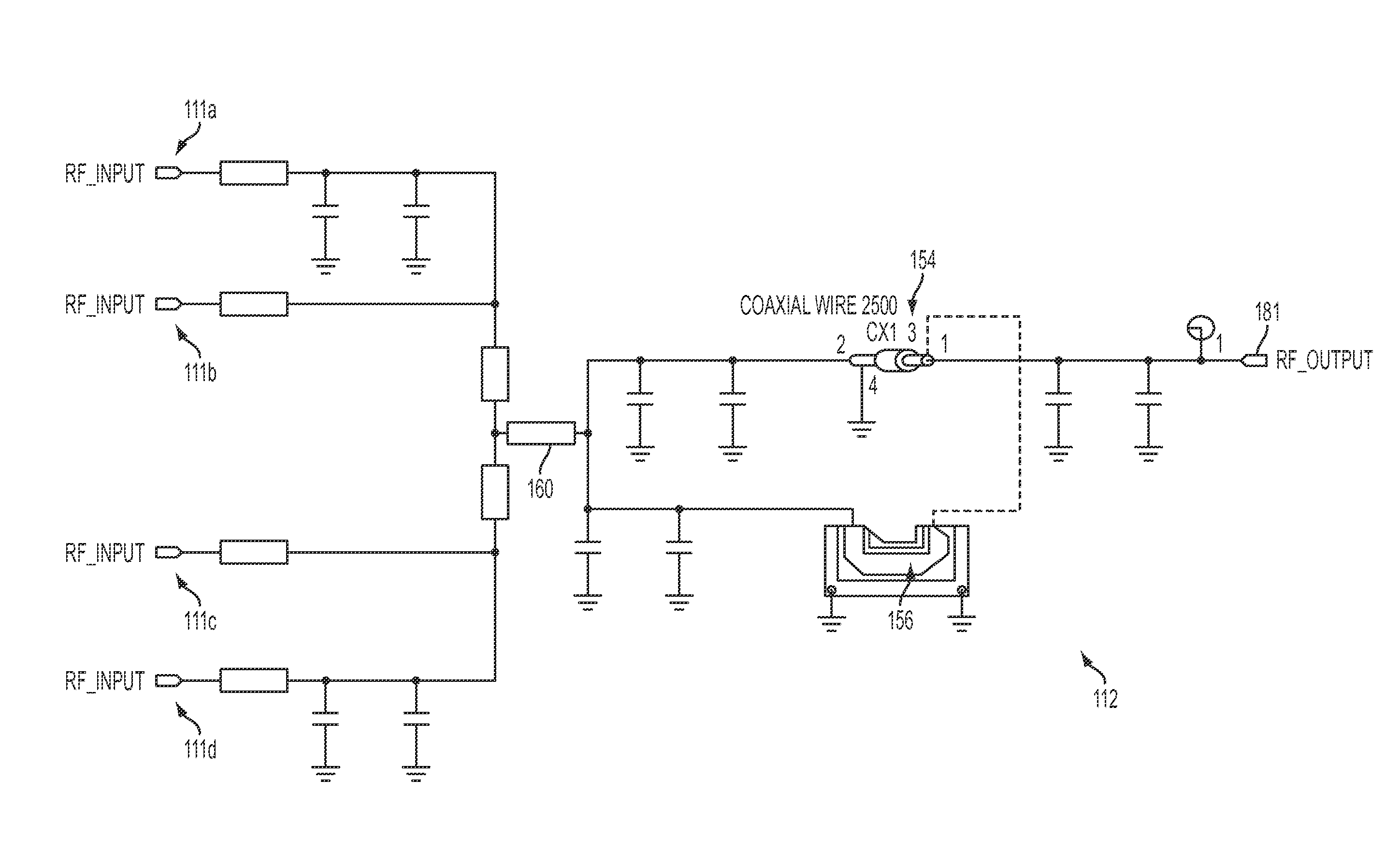
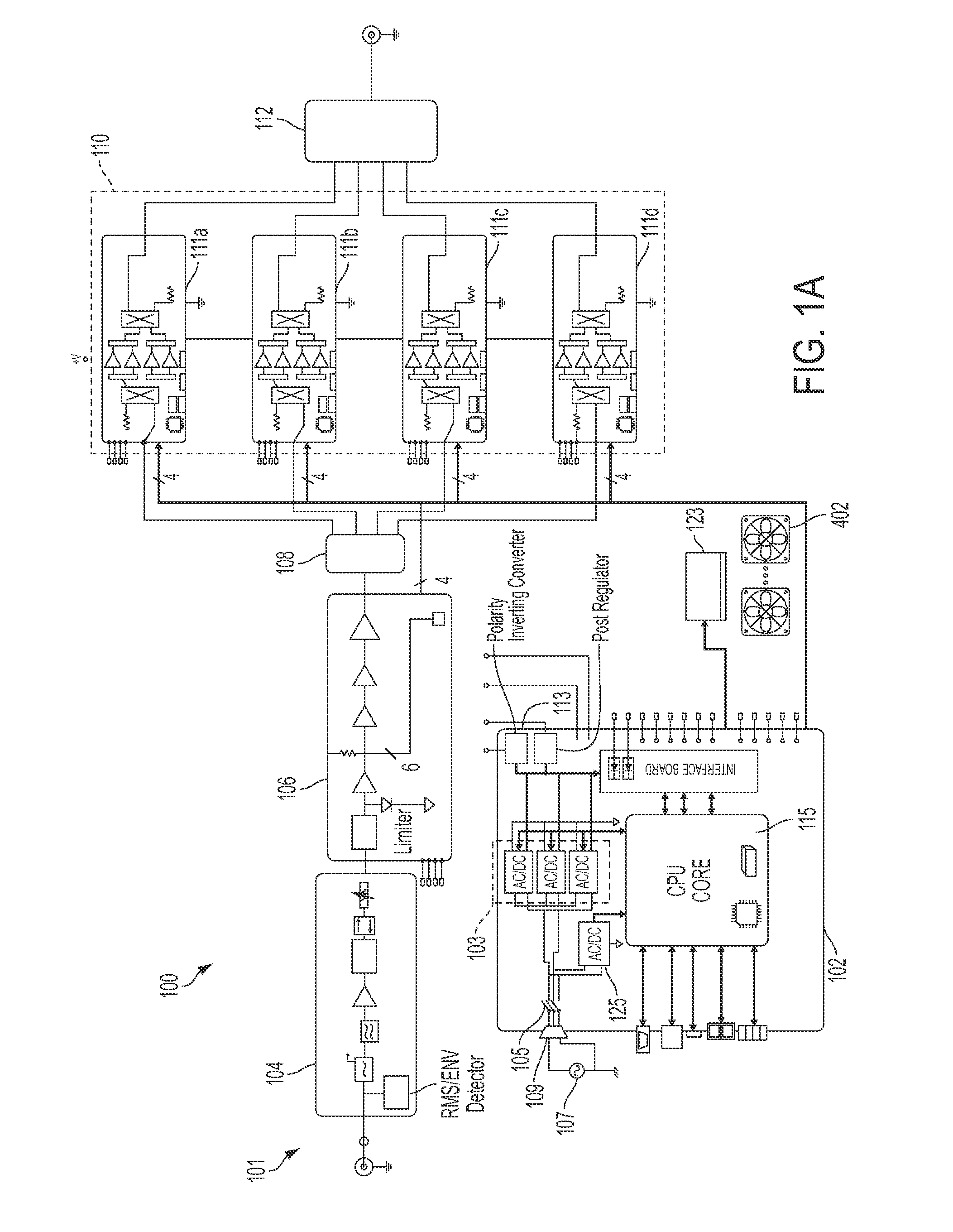
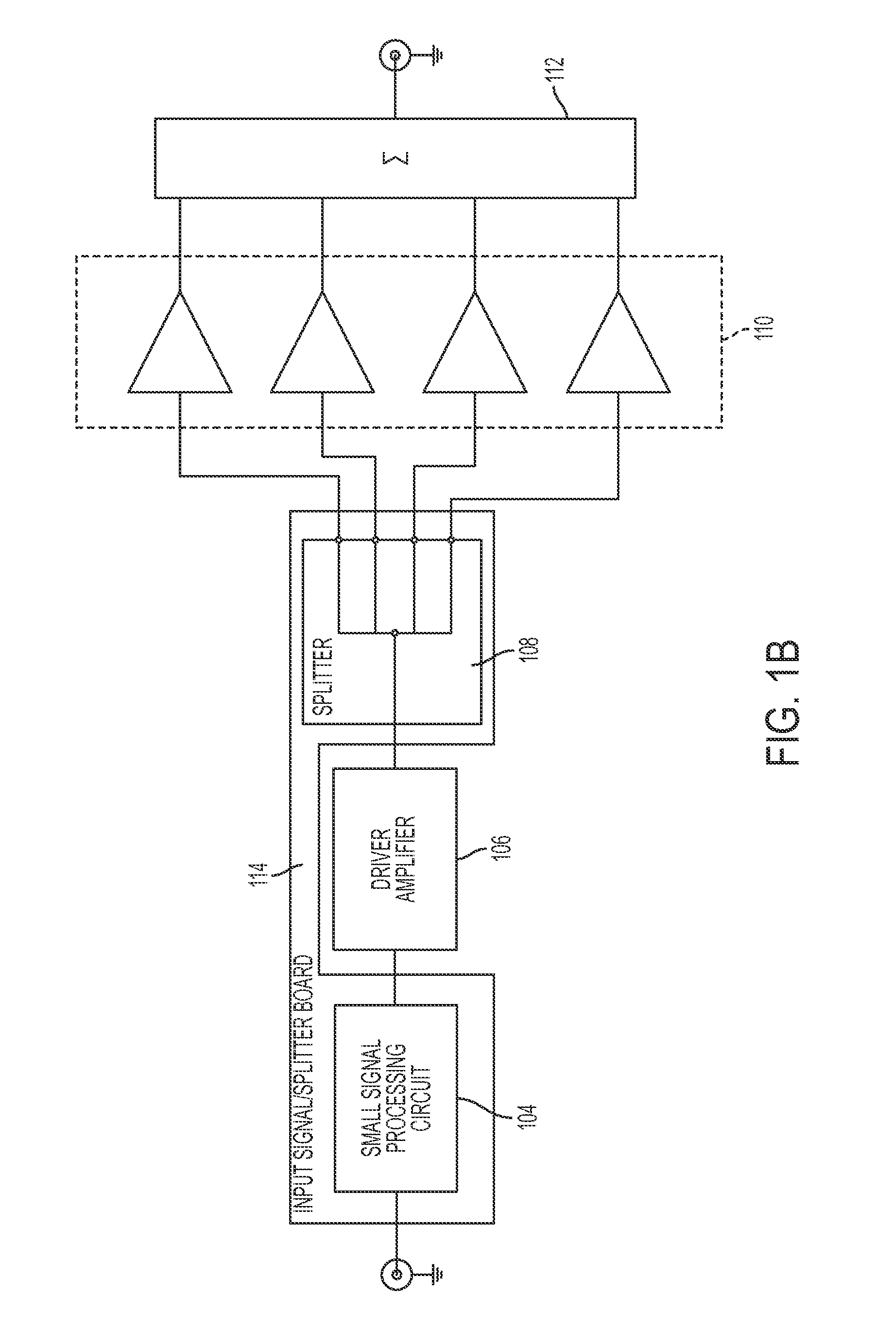
[0026]In general, an RF power amplifier comprises a controller, a driver, a splitter, a final stage, and a combiner coupled together to function as the RF power amplifier. One or more of the above components are arranged on one or more motherboards, e.g., a printed circuit board (PCB). However, in a preferred embodiment, the motherboard includes electrical components for at least the splitter. In other embodiments, the motherboard may include the controller and splitter, and in some other embodiments the controller and splitter may be disposed on separate printed ci...


PUM


Abstract

In general, an RF power amplifier comprises a controller, a driver, a splitter, a final stage, and a combiner coupled together to function as the RF power amplifier. One or more of the above components are arranged on one or more motherboards, e.g., a printed circuit board (PCB). A heat sink defines a base of the RF power amplifier, and in some embodiments includes at least two grooves formed therein, wherein the electrical components of the splitter and electrical components of the controller fit within one or more of the grooves so that these components can substantially disposed within the heat sink. In some embodiments, a power rail is also provided, and is also disposed substantially within the heat sink. The power rail groove of the heat sink and the carrier of the final stage provide an EMI shield of the power rail.

Description

FIELD OF THE INVENTION[0001]This invention relates generally to the field of RF power amplifiers and more particularly to an architecture for an RF power amplifier. This invention also relates generally to the field of combiners for RF power amplifiers.BACKGROUND[0002]An RF power amplifier is a type of electronic amplifier used to convert a low-power radio-frequency signal into a larger signal of significant power, typically for driving the antenna of a transmitter. It is usually optimized to have high efficiency and high output power, while minimizing heat dissipation. The basic RF amplifier apparatus includes an input circuit, a splitter, a final stage and a combiner that operate together to deliver the amplified output.[0003]Existing RF amplifiers have problems. The RF amplifier assembly described above is difficult to manufacture, involves multiple assembly steps, and the assembly process is error prone. For example, each of the input signal circuit, splitter, modules of the fin...

Claims


Application Information

Patent Timeline
Patent Type & Authority Patents(United States)
IPC IPC(8): H03F1/00H03F3/21
CPCH03F3/211H05K7/20563
Inventor CORREA, PAULOWIKE, DONALD M.MOGILEVSKY, LEONID
Owner EMPOWER RF SYST
Why Eureka
Try Eureka