Windscreen wiper drive control system and method

a technology of drive control and wiper, which is applied in adaptive control, vehicle cleaning, instruments, etc., can solve the problems of unlikely operation and malfunction, and achieve the effects of saving management, storage and production costs, reducing speed or stopping, and increasing configuration speed

Active Publication Date: 2015-04-14
ROBERT BOSCH GMBH
View PDF6 Cites 20 Cited by
  • Summary
  • Abstract
  • Description
  • Claims
  • Application Information

AI Technical Summary

Benefits of technology

[0005]In order to equip or provide a motor vehicle with windscreen wiper systems or replacement parts, it is consequently no longer required to differentiate between different drive control means. Management, storage and production costs can therefore be saved. Moreover, it is readily possible to change an existing distribution of the master or slave roles onto two drive control means by removing the connection of the control module to the first interface of one of the drive control means and connecting it instead to the first interface of the other drive control means.
[0006]The drive control means can configure itself as slave in the event that no control information could be received via the first interface over a predetermined period of time. As a result, a configuration of a plurality of drive control means as master in a system, which can lead to operational malfunctions, is unlikely. The configuration as master or as slave can be reversed by control information being received via the first interface, which if need be triggers a new configuration of the drive control means, parallel to an operation in the respective role. This increases a configuration speed and allows the drive control means to be more easily managed.
[0007]The drive control means can be configured to exchange control information, which comprises a target position and an actual position of a drive that is connected to one of the drive control means, via the second interface. In so doing, the drive control means configured as master can transmit a target position and receive an actual position. A collision detection can, for example, be implemented using this information if one of the wiper arms meets resistance and continues operation at a reduced speed or stops. The drive control means configured as master can resolve such a collision by allowing one or both of the drives to run in a predetermined sequence and at a predetermined speed in a suitable direction.
[0008]The drive control means can access at least two stored characteristic curves and in a configuration in the master role control the drive according to a first characteristic curve and in a configuration in the slave role according to a second characteristic curve. The characteristic curves define a temporal course of a movement of the drive or respectively the wiper arm. A characteristic course of movement of a drive connected to the drive control means can therefore vary depending upon whether said drive control means is configured as master or as slave. This allows for an interaction in the course of movement of the drives to change by reconfiguring the master and slave roles. In addition, a communication complexity between two drive control means is minimized by the local processing of characteristic curves.
[0009]The drive control means can be arranged to configure itself as slave in cases of doubt, for instance after receiving control information via the first as well as the second interface. Mechanical and data collisions can thereby be avoided if both drive control means try to assume the master role.

Problems solved by technology

As a result, a configuration of a plurality of drive control means as master in a system, which can lead to operational malfunctions, is unlikely.

Method used


Image

  • Windscreen wiper drive control system and method
  • Windscreen wiper drive control system and method
  • Windscreen wiper drive control system and method

Examples


Embodiment Construction

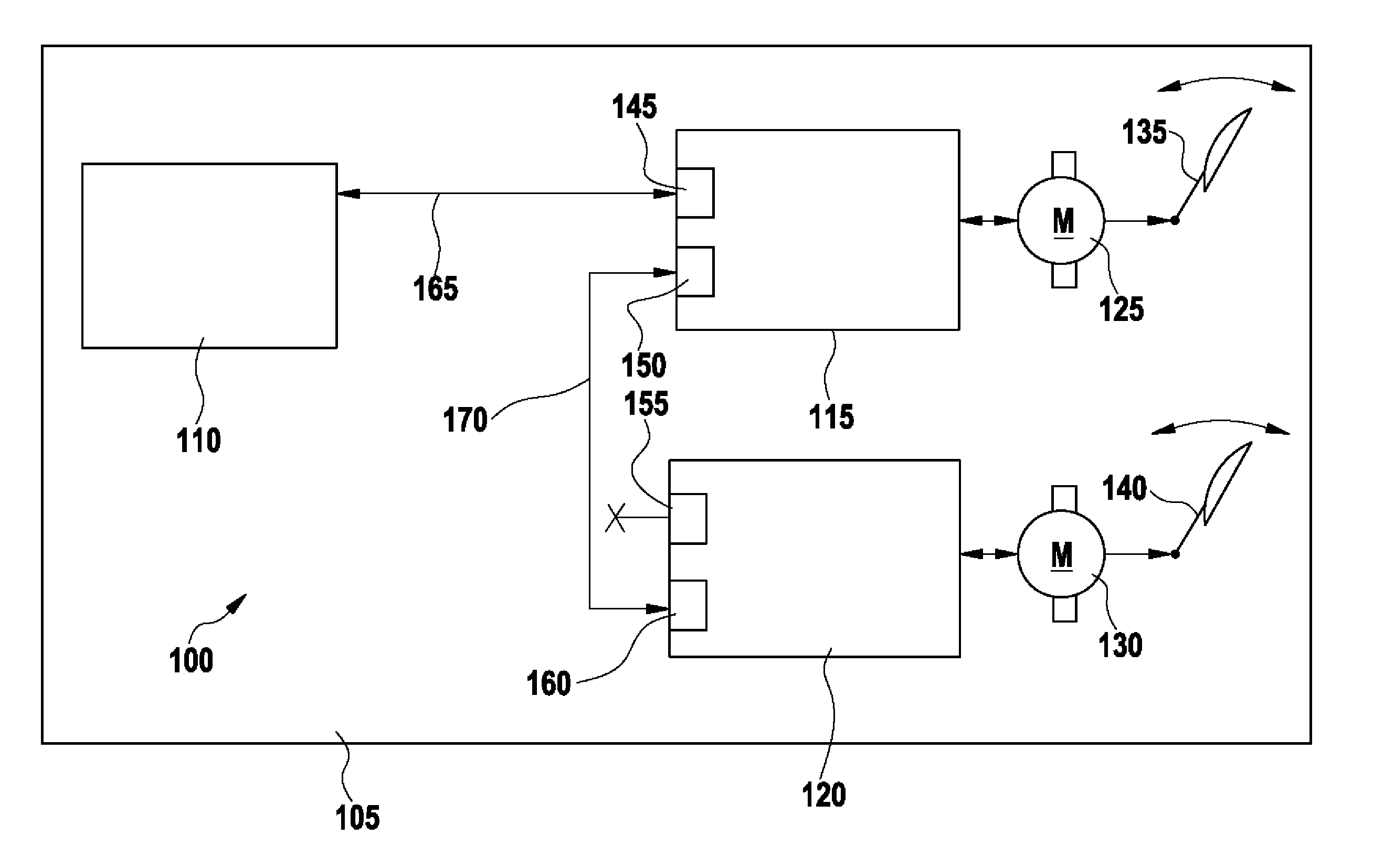
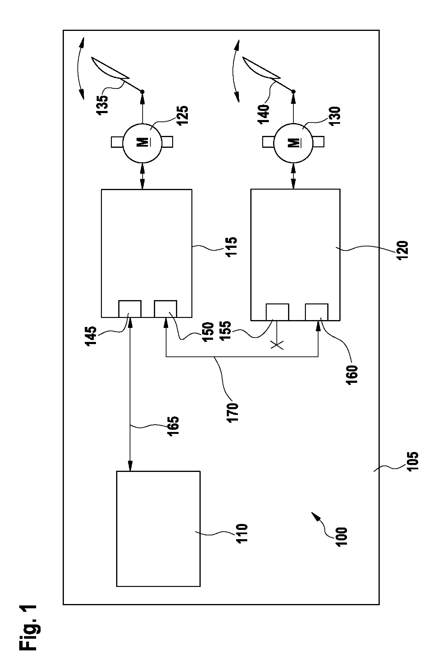
[0017]FIG. 1 shows a control system 100 for windscreen wipers in a motor vehicle 105. The control system 100 comprises a control module 110, a first drive control means 115 and a second drive control means 120. A first drive 125 is associated with the first drive control means 115 and a second drive 130 is associated with the second drive control means 120. The first drive 125 operates a first wiper arm 135 and the second drive 130 operates a second wiper arm 140. Said first drive control means 115 comprises a first interface 145 and a second interface 150. Said second drive control means 120 comprises a first interface 155 and a second interface 160. The control module 110 is connected to a first interface 145 of said first drive control means 115 by means of a first connection 165. A second connection 170 runs from the second interface 150 of said first drive control means 115 to the second interface 160 of said second drive control means 120.

[0018]The control module 110 is a part...


PUM


Abstract

The invention relates to a drive control means, in particular for controlling a windscreen wiper drive of a motor vehicle, having a first interface and a second interface, wherein, after receiving control information via the first interface, the drive control means is arranged to configure itself in a master role and to output control information via the second interface in order to control a further drive control means.

Description

BACKGROUND OF THE INVENTION[0001]The invention relates to a drive control means, in particular for controlling a windscreen wiper drive of a motor vehicle.[0002]Motor vehicles have windscreen wipers in order to clear moisture and dirt from the window panes of the motor vehicle. A windscreen wiper comprises a drive, a wiper arm and a wiper blade. The drive transmits an oscillating movement to the wiper arm, which guides the wiper blade across the window pane. Windscreens of passenger cars are normally equipped with two adjacent wipers. In order to avoid a mechanical connection between the wiper arms of both windscreen wipers, each windscreen wiper can have its own drive associated therewith, wherein the drives are synchronized in order to prevent a collision of the wiper arms or respectively the wiper blades and in order to maintain a predetermined sequence of movement of the windscreen wipers. Each of the drives comprises a control means associated therewith. Depending upon the conf...

Claims


Application Information

Patent Timeline
Patent Type & Authority Patents(United States)
IPC IPC(8): G06F7/00B60S1/08
CPCB60S1/0814
Inventor PRSKAWETZ, PHILIPPTISCH, FLORIANFABING, EDGARD
Owner ROBERT BOSCH GMBH
Why Eureka
Try Eureka