
Internal circulation ball screw

a circulation ball screw and ball screw technology, applied in the field of ball screw, can solve the problems of b>3/b> being subject to damage, the nut is too long, and the ineffective threads become mor

Active Publication Date: 2015-04-21
HIWIN TECH
View PDF35 Cites 4 Cited by
  • Summary
  • Abstract
  • Description
  • Claims
  • Application Information

AI Technical Summary

Benefits of technology

[0006]The primary objective of the present invention is to provide an internal circulation ball screw, the durability of which can be enhanced.
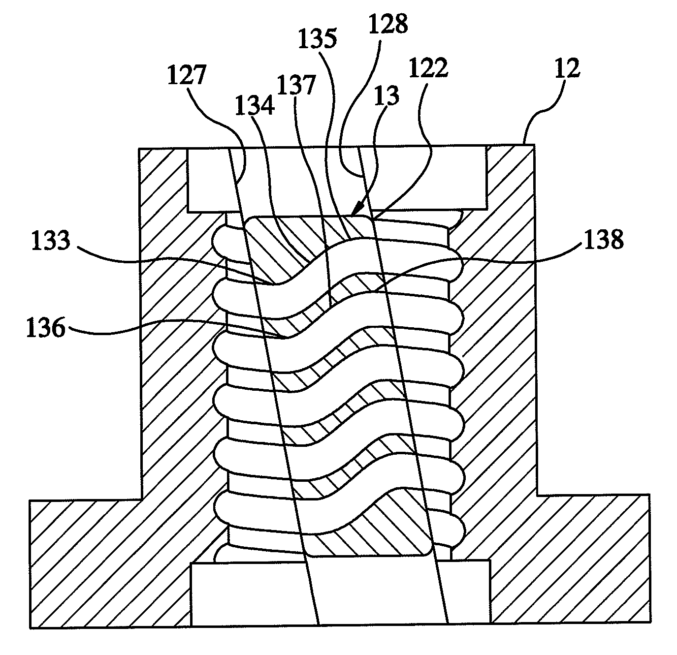
[0008]Therefore, the present invention can avoid applying the cross-thread design to the circulation member and the walls of the circulation channels are uniform.

Problems solved by technology

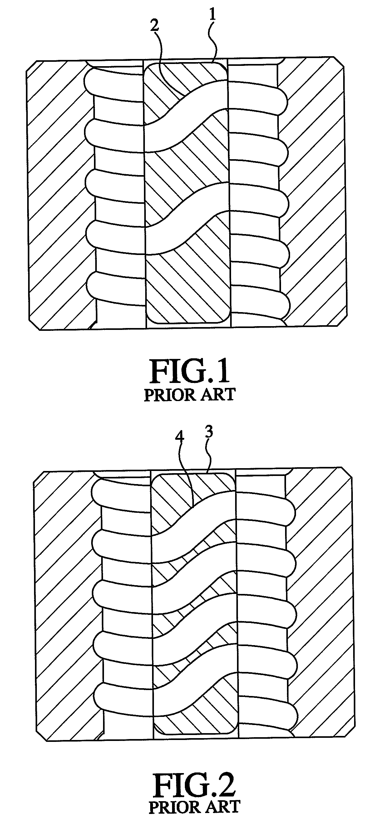
However, the cross-thread design will result in that the nut is too long and the ineffective threads become more.
In addition, the pitch between the adjacent circulation channels 4 provided by the circulation member 3 shown in FIG. 2 for the rolling members to cross the peak of the thread is too small and the walls of the circulation channels 4 are thin, so the circulation member 3 is subject to damage.

Method used


Image

  • Internal circulation ball screw
  • Internal circulation ball screw
  • Internal circulation ball screw

Examples


Embodiment Construction

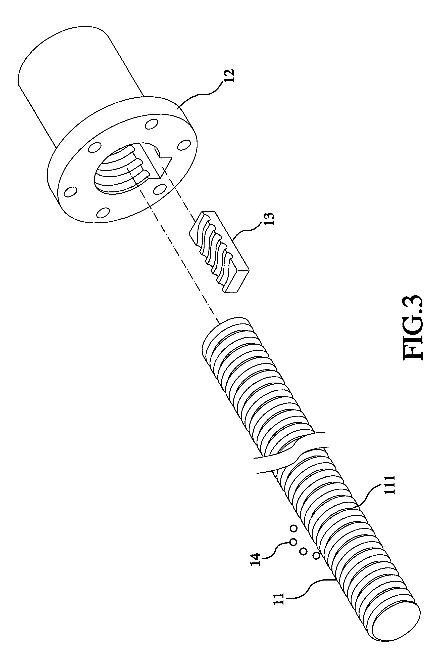
[0024]Referring to FIGS. 3-9, an internal circulation ball screw constructed according to a first preferred embodiment of the present invention is composed of a threaded shaft 11, a nut 12, a circulation member 13, and a plurality of rolling members 14. The detailed descriptions and operations of these elements as well as their interrelations are recited in the respective paragraphs as follows.

[0025]The threaded shaft 11 includes a first threaded groove 111 and an imaginary axis 112.

[0026]The nut is sleeved onto the threaded shaft 11 and includes a second threaded groove 121 and a receiving space 122. The second threaded groove 121 corresponds to and fits the first threaded groove 111. The receiving space 122 is provided with a first side 127 and a second side 128. The second threaded groove 121 intersects the receiving space 122 in such a way that a first fracture 123 and a third fracture 125 are formed at the first side 127 and a second fracture 124 and a fourth fracture 126 are f...


PUM


Abstract

An internal circulation ball screw includes a threaded shaft, a nut having a receiving space, a circulation member mounted to the receiving space and having a first circulation groove and a second circulation groove, and a plurality of rolling members running between the threaded shaft and the nut. The first circulation groove defines a first front section, a first rear section, and a first curved section communicating with the first front section and the first rear section separately. The second circulation groove defines a second front section, a second rear section, and a second curved section communicating with the second front section and the second rear section separately. The first and second curved sections define a predetermined included angle with respect to the threaded shaft radially. Therefore, the wall between the circulation channels is uniform to enhance the durability of the ball screw.

Description

BACKGROUND OF THE INVENTION[0001]1. Field of the Invention[0002]The present invention relates generally to a ball screw, and more particularly, to an internal circulation ball screw.[0003]2. Description of the Related Art[0004]A generic ball screw includes two types—external circulation ball screw and internal circulation ball screw. In the external circulation ball screw, a guiding member is mounted to a nut for guiding circulative movement of rolling members. Generally speaking, the external circulation ball screw is applicable while the pitch is longer and the nut is bigger relatively. As for the internal circulation ball screw, a circulation member is additionally mounted inside the nut to allow circulative movement of the rolling members inside the nut, so the internal circulation ball screw is applicable while the pitch is shorter and the nut is smaller relatively.[0005]The conventional internal circulation ball screw includes a circulation member, which is usually linearly ar...

Claims


Application Information

Patent Timeline
Patent Type & Authority Patents(United States)
IPC IPC(8): F16H25/22
CPCF16H25/2223F16H25/2219Y10T74/19767Y10T74/19753Y10T74/19772
Inventor CHEN, YAN-YULIN, YUNG-HSUEH
Owner HIWIN TECH
Learn More