Optical microphone

a microphone and optical technology, applied in the field of optical microphones, can solve the problems of affecting the detection accuracy of microphones, so as to achieve the effect of increasing the detection sensitivity

Active Publication Date: 2015-04-21
PANASONIC INTELLECTUAL PROPERTY MANAGEMENT CO LTD
View PDF20 Cites 3 Cited by
  • Summary
  • Abstract
  • Description
  • Claims
  • Application Information

AI Technical Summary

Benefits of technology

[0016]The optical microphone disclosed in the present application detects not interference of light but a rotation of a polarization plane of light due to optical birefringence caused in the acoustic medium by the application of the acoustic signal thereto. Therefore, it is possible to configure an optical microphone without using a narrow-range light source, acousto-optic modulators and an optical interferometer. Therefore, it is possible to realize an optical microphone that is small and highly resistant against ambient environment fluctuations.
[0017]As it further includes an elliptically-polarized light generation section, it is possible to further increase the detection sensitivity.

Problems solved by technology

Therefore, the characteristics of the diaphragm may possibly deteriorate while using the microphone repeatedly.
When an acoustic signal of a high intensity is detected using the microphone, the diaphragm of the microphone may possibly be vibrated significantly by the acoustic signal, thereby breaking the diaphragm.
Moreover, one cannot expect a microphone to detect a desirable acoustic signal at frequencies greater than or equal to the lowest resonance frequency of the diaphragm.
Therefore, it is difficult for a microphone to detect frequencies over a wide range (hereinafter referred to as the “wide-range property”.).

Method used


Image

  • Optical microphone
  • Optical microphone
  • Optical microphone

Examples


first embodiment

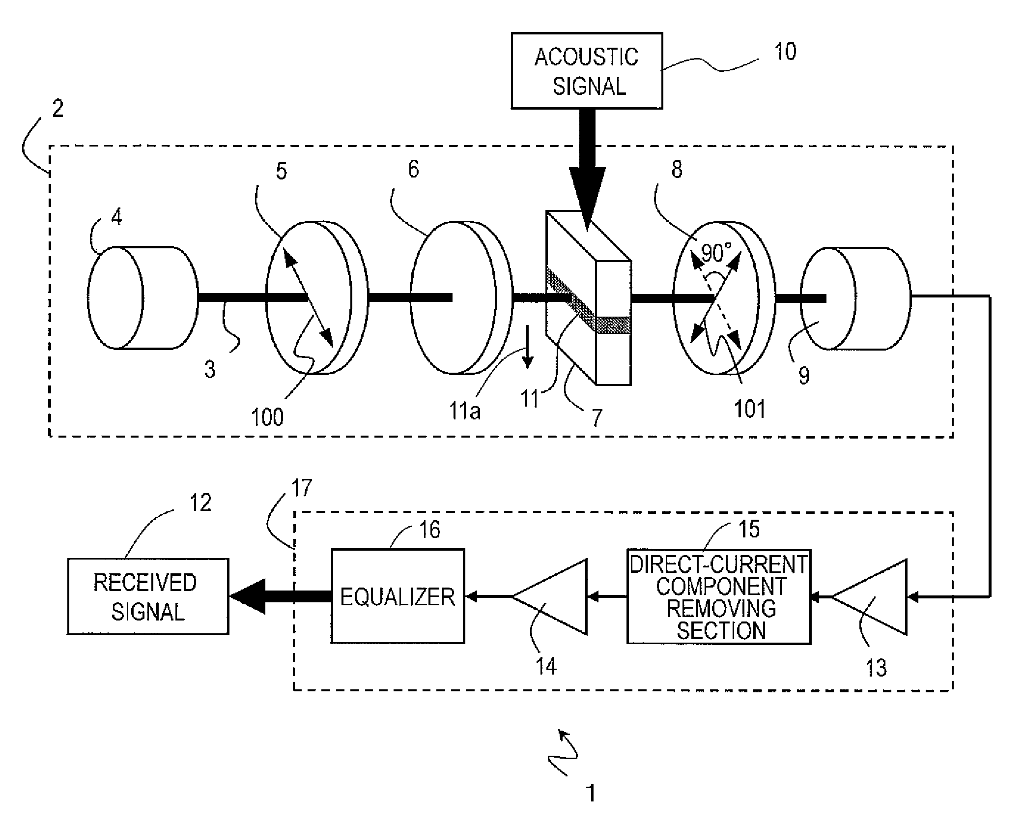
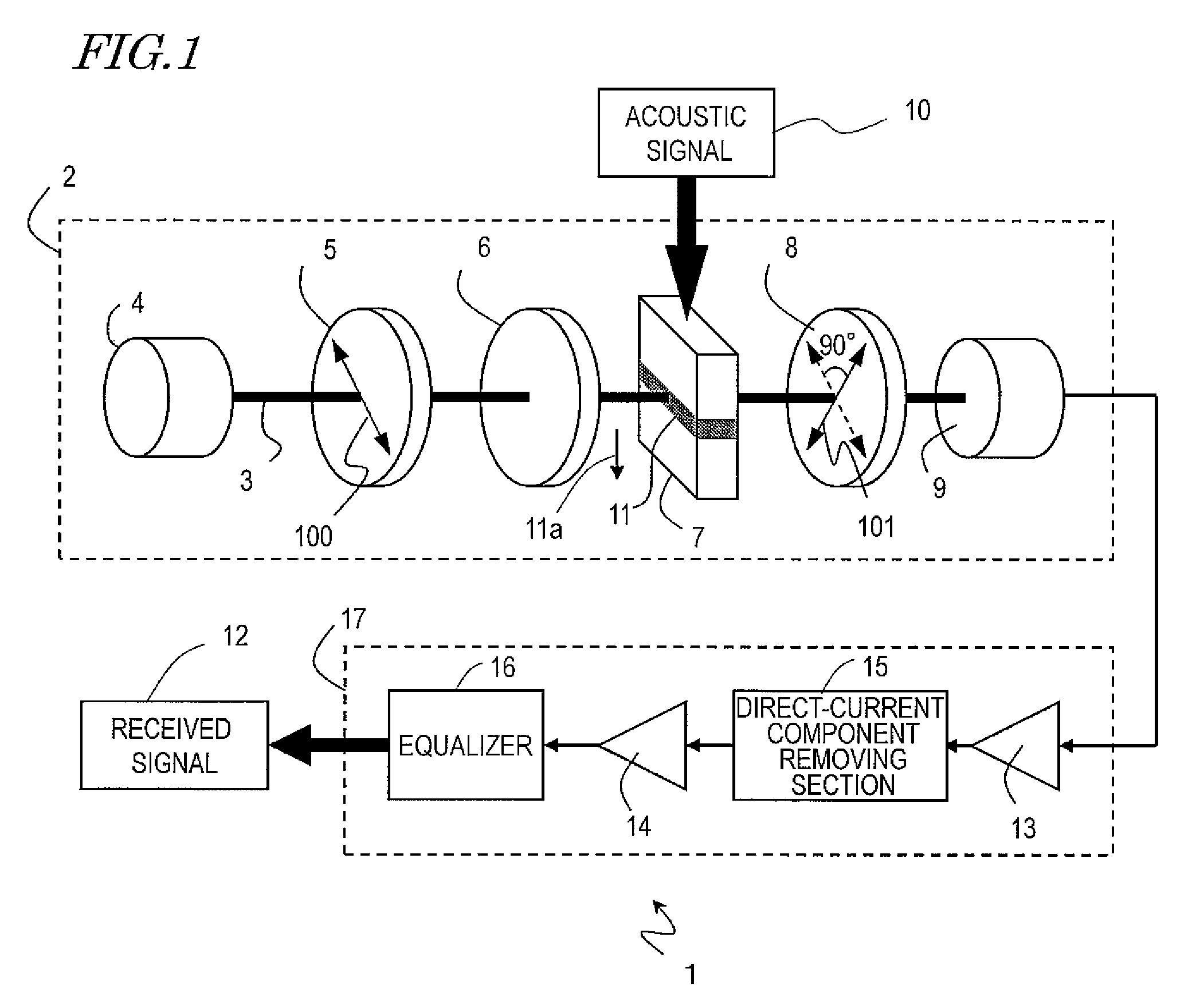
[0064]FIG. 1 shows a configuration of a first embodiment of an optical microphone of the present invention. An optical microphone 1 includes a detection optical system 2 and a signal processing system 17. The detection optical system 2 detects an acoustic signal propagating through the environment around the optical microphone 1 to produce an electric signal, and the signal processing system 17 performs a signal process on the electric signal, thereby producing a received signal 12. The components will now be described.

2>

[0065]The detection optical system 2 includes a light source 4, a first polarizer 5, an elliptically-polarized light generation section 6, a sound-receiving section 7, a second polarizer 8, and a photodetector 9.

[0066]The light source 4 outputs a light beam 3. The light beam 3 used in the present embodiment may be coherent light or may be incoherent light. The occupied wavelength range of the light beam 3 may be a single or narrow range or may be a wide range. This ...

second embodiment

[0144]FIG. 16 shows a configuration of a second embodiment of an optical microphone of the present invention. An optical microphone 1′ includes a detection optical system 2′ and the signal processing system 17. As in the first embodiment, the detection optical system 2′ is used to detect an acoustic signal propagating through the environment around the optical microphone 1′ to generate an electric signal, and the signal processing system performs a signal process on the electric signal, thereby generating the received signal 12. In FIG. 16, like components to those of the first embodiment are denoted by like reference numerals. In the present embodiment, a ¼ wave plate 92 is used as the elliptically-polarized light generation section 6.

[0145]In the optical microphone 1′, the relative angle between the optical axes of the first polarizer 5, the second polarizer 8 and the ¼ wave plate 92 used as the elliptically-polarized light generation section 6 is different from the first polarize...

third embodiment

[0154]FIGS. 19A to 19D show a third embodiment of an optical microphone according to the present invention. Although the signal processing section is not shown in these embodiment, the signal processing section described above in the first and second embodiments is included. In the first and second embodiments, either one of the detection optical systems 2 and 2′ has its components arranged in a line along the light beam 3. However, the components of the detection optical systems 2 and 2′ do not have to be arranged in a line. In the present embodiment, the optical path of the detection optical system is formed by using reflected light.

[0155]The optical microphone shown in FIG. 19A includes the light source 4, the first polarizer 5, the elliptically-polarized light generation section 6, the second polarizer 8, the photodetector 9, the sound-receiving section 7, a beam splitter 201, and a mirror 202.

[0156]The light beam 3 output from the light source passes through the first polarizer...


PUM


Abstract

An optical microphone includes: a light source; a first polarizer for allowing linearly-polarized light, of light output from the light source, to pass therethrough; a second polarizer for allowing linearly-polarized light having a different polarization plane from the first polarizer to pass therethrough; a sound-receiving section including an acoustic medium having a smaller sound velocity than the air, wherein an acoustic signal propagates through the acoustic medium, the sound-receiving section being arranged so that the linearly-polarized light from the first polarizer passes through the acoustic medium and enters the second polarizer; and a photodetector for converting an intensity of light having passed through the second polarizer to an electric signal, wherein between the first polarizer and the second polarizer, the linearly-polarized light having passed through the first polarizer is given different phase shifts in two orthogonal directions which are each different from a polarization direction.

Description

[0001]This is a continuation of International Application No. PCT / JP2012 / 002315, with an international filing date of Apr. 3, 2012, which claims priority of Japanese Patent Application No. 2011-083682, filed on Apr. 5, 2011, the contents of which are hereby incorporated by reference.BACKGROUND[0002]1. Technical Field[0003]The present application relates to an optical microphone for detecting an acoustic signal using light.[0004]2. Description of the Related Art[0005]Microphones for detecting an acoustic signal using a diaphragm and converting the acoustic signal to an electrical signal have been widely used in the art. Such a microphone includes a diaphragm, which is a mechanically vibrating portion. Therefore, the characteristics of the diaphragm may possibly deteriorate while using the microphone repeatedly. When an acoustic signal of a high intensity is detected using the microphone, the diaphragm of the microphone may possibly be vibrated significantly by the acoustic signal, th...

Claims


Application Information

Patent Timeline
Patent Type & Authority Patents(United States)
IPC IPC(8): H04B10/112H04B10/114H04R23/00
CPCH04R23/008H04B10/114H04R2410/00
Inventor SANGAWA, USHIOIWAMOTO, TAKUYAKANEKO, YURIKOHASHIMOTO, MASAHIKO
Owner PANASONIC INTELLECTUAL PROPERTY MANAGEMENT CO LTD
Why Eureka
Try Eureka