Optical microphone
- Summary
- Abstract
- Description
- Claims
- Application Information
AI Technical Summary
Benefits of technology
Problems solved by technology
Method used
Image
Examples
first embodiment
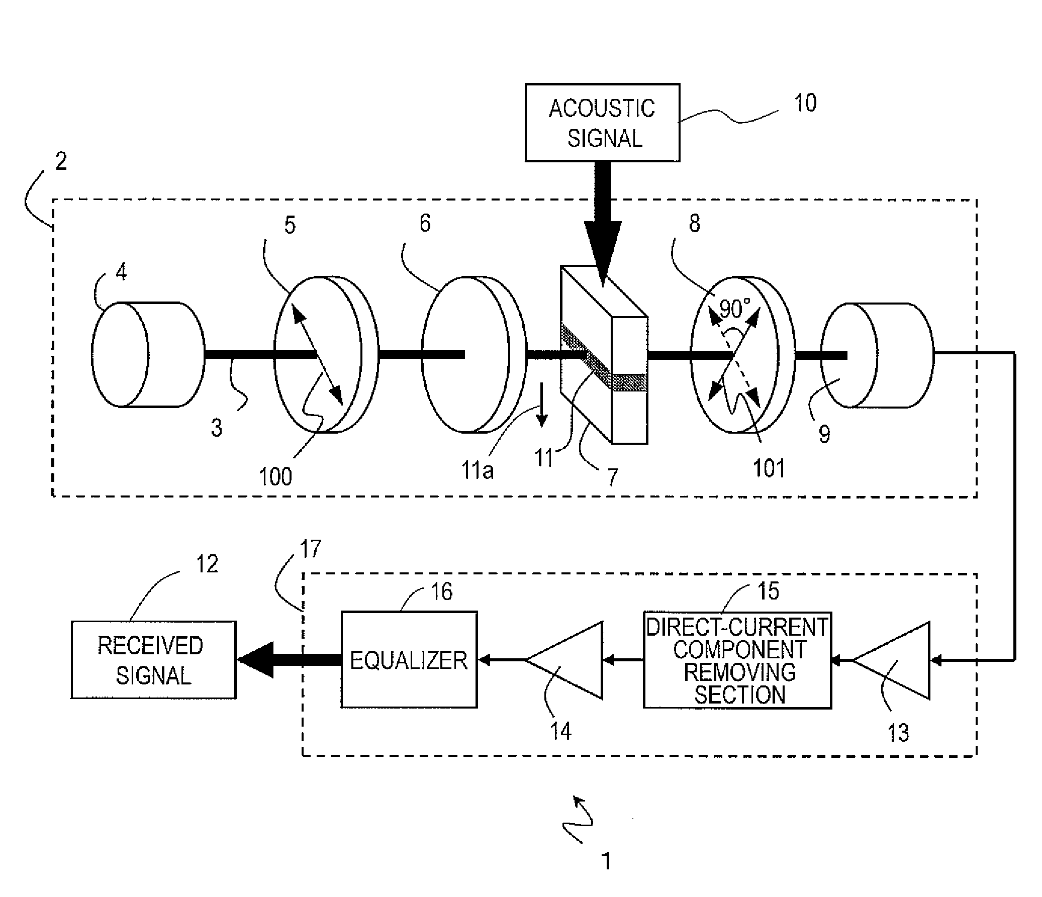
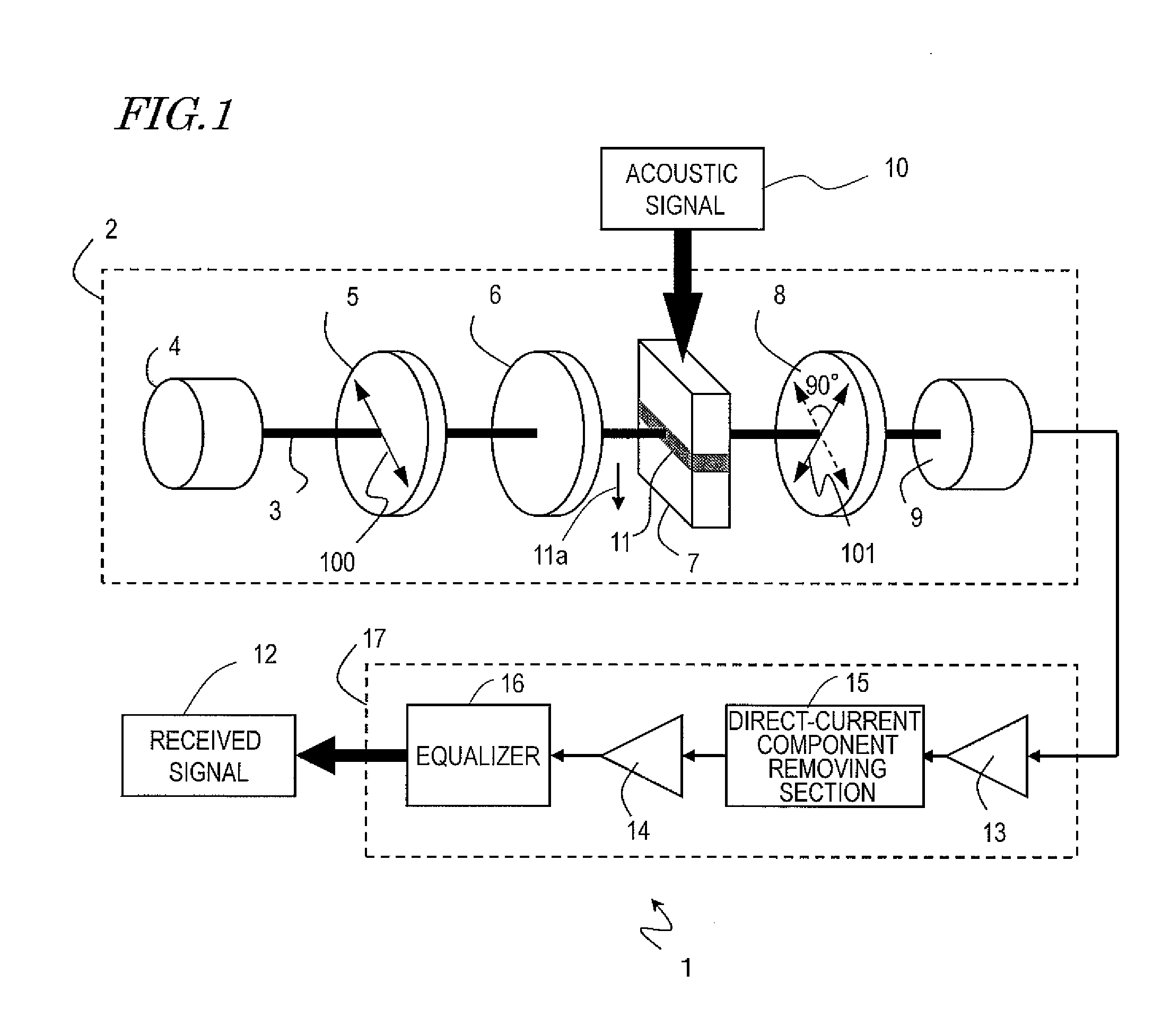
[0064]FIG. 1 shows a configuration of a first embodiment of an optical microphone of the present invention. An optical microphone 1 includes a detection optical system 2 and a signal processing system 17. The detection optical system 2 detects an acoustic signal propagating through the environment around the optical microphone 1 to produce an electric signal, and the signal processing system 17 performs a signal process on the electric signal, thereby producing a received signal 12. The components will now be described.
2>
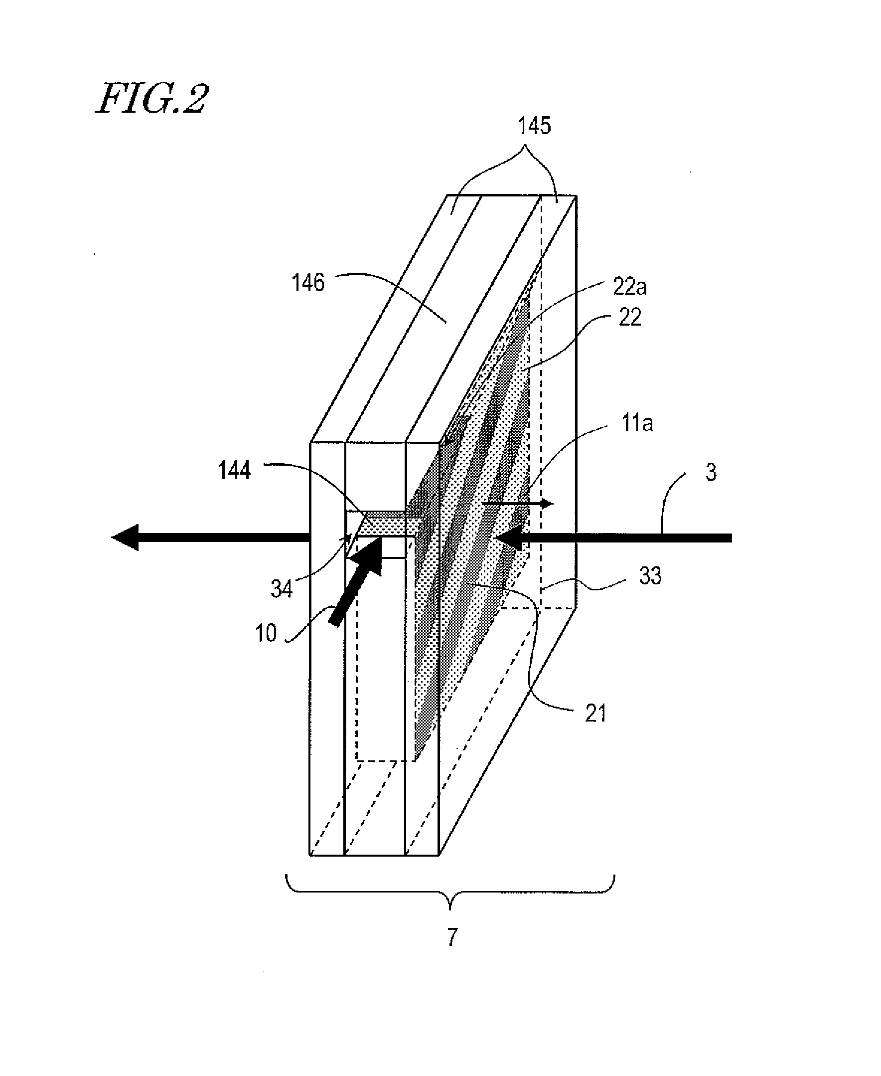
[0065]The detection optical system 2 includes a light source 4, a first polarizer 5, an elliptically-polarized light generation section 6, a sound-receiving section 7, a second polarizer 8, and a photodetector 9.
[0066]The light source 4 outputs a light beam 3. The light beam 3 used in the present embodiment may be coherent light or may be incoherent light. The occupied wavelength range of the light beam 3 may be a single or narrow range or may be a wide range. This ...
second embodiment
[0143]FIG. 16 shows a configuration of a second embodiment of an optical microphone of the present invention. An optical microphone 1′ includes a detection optical system 2′ and the signal processing system 17. As in the first embodiment, the detection optical system 2′ is used to detect an acoustic signal propagating through the environment around the optical microphone 1′ to generate an electric signal, and the signal processing system performs a signal process on the electric signal, thereby generating the received signal 12. In FIG. 16, like components to those of the first embodiment are denoted by like reference numerals. In the present embodiment, a ¼ wave plate 92 is used as the elliptically-polarized light generation section 6.
[0144]In the optical microphone 1′, the relative angle between the optical axes of the first polarizer 5, the second polarizer 8 and the ¼ wave plate 92 used as the elliptically-polarized light generation section 6 is different from the first polarize...
third embodiment
[0153]FIGS. 19A to 19D show a third embodiment of an optical microphone according to the present invention. Although the signal processing section is not shown in these embodiment, the signal processing section described above in the first and second embodiments is included. In the first and second embodiments, either one of the detection optical systems 2 and 2′ has its components arranged in a line along the light beam 3. However, the components of the detection optical systems 2 and 2′ do not have to be arranged in a line. In the present embodiment, the optical path of the detection optical system is formed by using reflected light.
[0154]The optical microphone shown in FIG. 19A includes the light source 4, the first polarizer 5, the elliptically-polarized light generation section 6, the second polarizer 8, the photodetector 9, the sound-receiving section 7, a beam splitter 201, and a mirror 202.
[0155]The light beam 3 output from the light source passes through the first polarizer...
PUM
 Abstract
Description
Claims
Application Information
 - R&D
- Intellectual Property
- Life Sciences
- Materials
- Tech Scout
- Unparalleled Data Quality
- Higher Quality Content
- 60% Fewer Hallucinations
Browse by: Latest US Patents, China's latest patents, Technical Efficacy Thesaurus, Application Domain, Technology Topic, Popular Technical Reports.
© 2025 PatSnap. All rights reserved.Legal|Privacy policy|Modern Slavery Act Transparency Statement|Sitemap|About US| Contact US: help@patsnap.com


