Centrifugal ceiling fan

a ceiling fan and centrifugal technology, applied in the direction of wind motors with parallel air flow, wind motors with perpendicular air flow, liquid fuel engine components, etc., can solve the problems of unventilated space, unventilated area outside the radius of paddles, and unventilated space occupied by paddles, so as to make the fan safer

Inactive Publication Date: 2015-05-05
SECCARECCIA ALESSANDRO
View PDF129 Cites 22 Cited by
  • Summary
  • Abstract
  • Description
  • Claims
  • Application Information

AI Technical Summary

Benefits of technology

[0011]According to an embodiment, there is provided a centrifugal ceiling fan which comprises a centrifugal impeller instead of paddles for forced air current. This centrifugal impeller will be encased, thus eliminating any exterior rotating parts. This configuration will make the fan safer, considering that the paddles create a danger to any object nearing the device.

Problems solved by technology

This type of fans has several problems.
One of the problems is the uneven distribution of air throughout the room.
Therefore, the area outside the radius of the paddles remains unventilated.
Other problems associated with axial fans include the space occupied by the paddles and the safety concerns due to the fact that the paddles are exposed as they rotate.
Thus, to obtain the same ventilation results, the rotation speed has to be increased, which results in an increase in energy consumption and noise.

Method used


Image

  • Centrifugal ceiling fan
  • Centrifugal ceiling fan
  • Centrifugal ceiling fan

Examples


Embodiment Construction

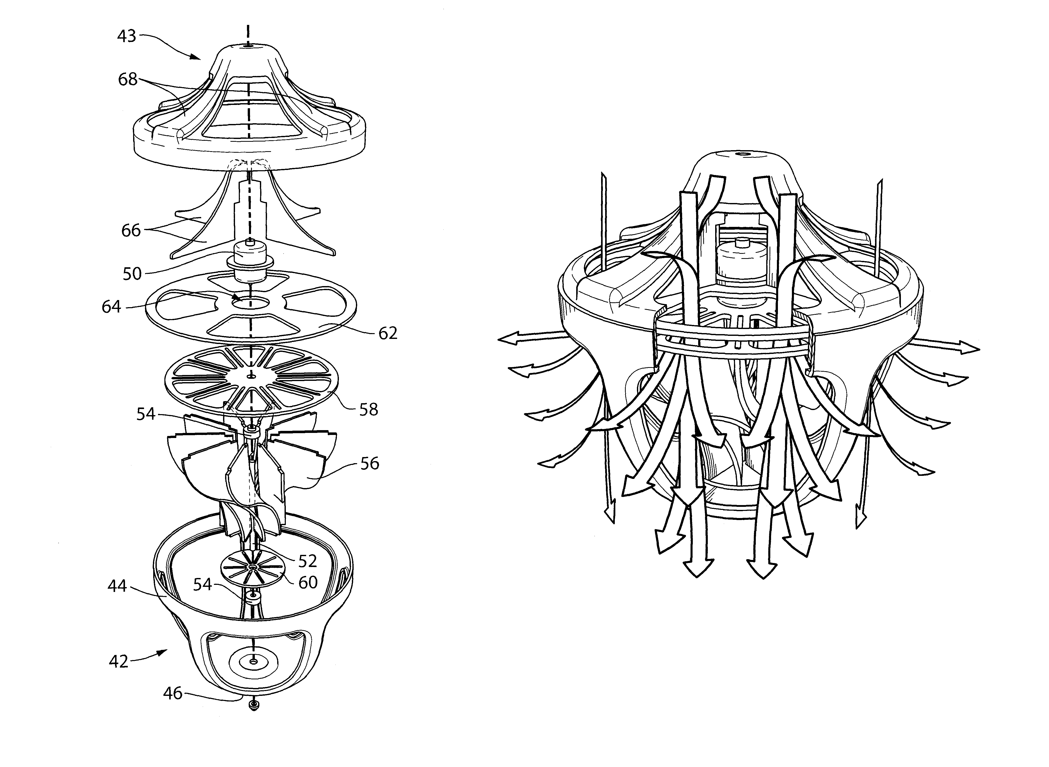
[0036]In embodiments there is disclosed a centrifugal ceiling fan. The fan comprises a casing, a motor and a centrifugal propeller. The casing comprises an upper surface comprising an air inlet and a lower surface comprising an air outlet. In an embodiment, the lower surface has a round bowl-like shape including a plurality of openings defining the air outlet. The propeller comprises a shaft and a plurality of blades provided around the shaft. The blades may be curved to push the air in all directions between a first direction substantially perpendicular to the rotation shaft and a second direction substantially parallel to the rotation shaft in order to evenly ventilate the room. The fan may include a heating element for heating the air as it exits from the fan.

[0037]Referring now to the drawings, FIG. 3 illustrates an example of a centrifugal ceiling fan in accordance with an embodiment. As shown in FIG. 3, the centrifugal ceiling fan 40 includes a casing. In an embodiment, the ca...


PUM


Abstract

The present document describes a centrifugal ceiling fan. The fan comprises a casing, a motor and a centrifugal propeller. The casing comprises an upper surface comprising an air inlet and a lower surface comprising an air outlet. In an embodiment, the lower surface has a round bowl-like shape including a plurality of openings defining the air outlet. The propeller comprises a shaft and a plurality of blades provided around the shaft. The blades may be curved to push the air in all directions between a first direction substantially perpendicular to the rotation shaft and a second direction substantially parallel to the rotation shaft in order to evenly ventilate the room. The fan may include a heating element for heating the air as it exits from the fan.

Description

CROSS-REFERENCE TO RELATED APPLICATIONS[0001]This application claims priority from U.S. Provisional Application No. 61 / 257,594, filed on Nov. 3, 2009, which is incorporated herein by reference in its entirety.BACKGROUND[0002](a) Field[0003]The subject matter disclosed generally relates to ceiling fans.[0004](b) Related Prior Art[0005]FIG. 1 illustrates a conventional axial ceiling fan 20. The ceiling fan 20 includes a plurality of paddles 22, a lamp 24, a motor 26 for turning the paddles 22, and attachment means 28 for attaching the ceiling fan 20 to the roof.[0006]This type of fans has several problems. One of the problems is the uneven distribution of air throughout the room. The paddles are mounted vertically to the axis of rotation and push the air downward in the same direction as the axis of rotation. Therefore, the area outside the radius of the paddles remains unventilated. Other problems associated with axial fans include the space occupied by the paddles and the safety con...

Claims


Application Information

Patent Timeline
Patent Type & Authority Patents(United States)
IPC IPC(8): F04D25/08F04D17/16F04D29/58F24H3/04
CPCF04D25/088F04D17/16F04D29/584F24H3/0405F04D29/281F05D2250/52F04D29/441F04D25/08F04D29/28F04D29/44F24H3/04F04D29/4226F04D13/06F04D29/4246
Inventor SECCARECCIA, ALESSANDRO
Owner SECCARECCIA ALESSANDRO
Why Eureka
Try Eureka