Signal conditioner for use in a burner control system

a technology of signal conditioner and burner control system, which is applied in the direction of combustion process, combustion measurement, combustion regulation, etc., can solve the problems of incompatibility of signals or signals produced by the controller with mechanical devices, inefficient operation, mechanical devices, etc., and achieve the effect of protecting equipment and preventing injury

Active Publication Date: 2015-05-05
MAXITROL
View PDF26 Cites 4 Cited by
  • Summary
  • Abstract
  • Description
  • Claims
  • Application Information

AI Technical Summary

Benefits of technology

[0011]By providing the delay circuit, the signal conditioner of the present invention prevents a possibly hazardous output signal from reaching the burner during start-up, thus safeguarding equipment and guarding against injury. Furthermore, by providing the temperature override circuit, the signal conditioner of the present invention prevents the burner from providing excessively high or low heating due to malfunctions in the controller or for energy management purposes.

Problems solved by technology

Often, the signal or signals produced by the controller are not compatible with the mechanical device to which they are intended control.
For instance, during start-up and / or power restoration to an HVAC system, the output signals provided by the controller could damage the mechanical device and / or result in inefficient operation.
Furthermore, failure in a temperature sensor or a program fault may result in the over heating or under heating of a burner and the entire HVAC system.

Method used


Image

  • Signal conditioner for use in a burner control system
  • Signal conditioner for use in a burner control system
  • Signal conditioner for use in a burner control system

Examples


Embodiment Construction

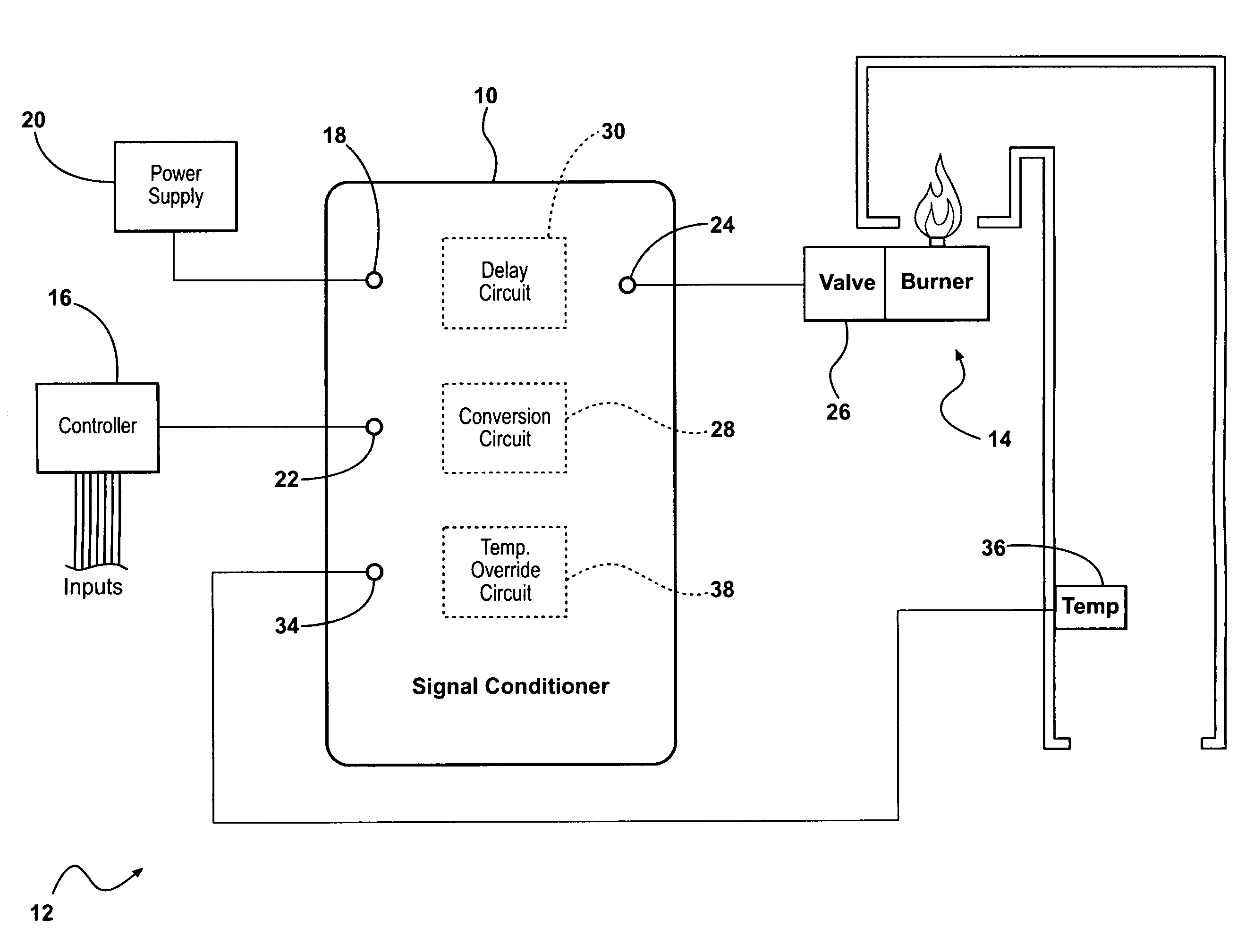
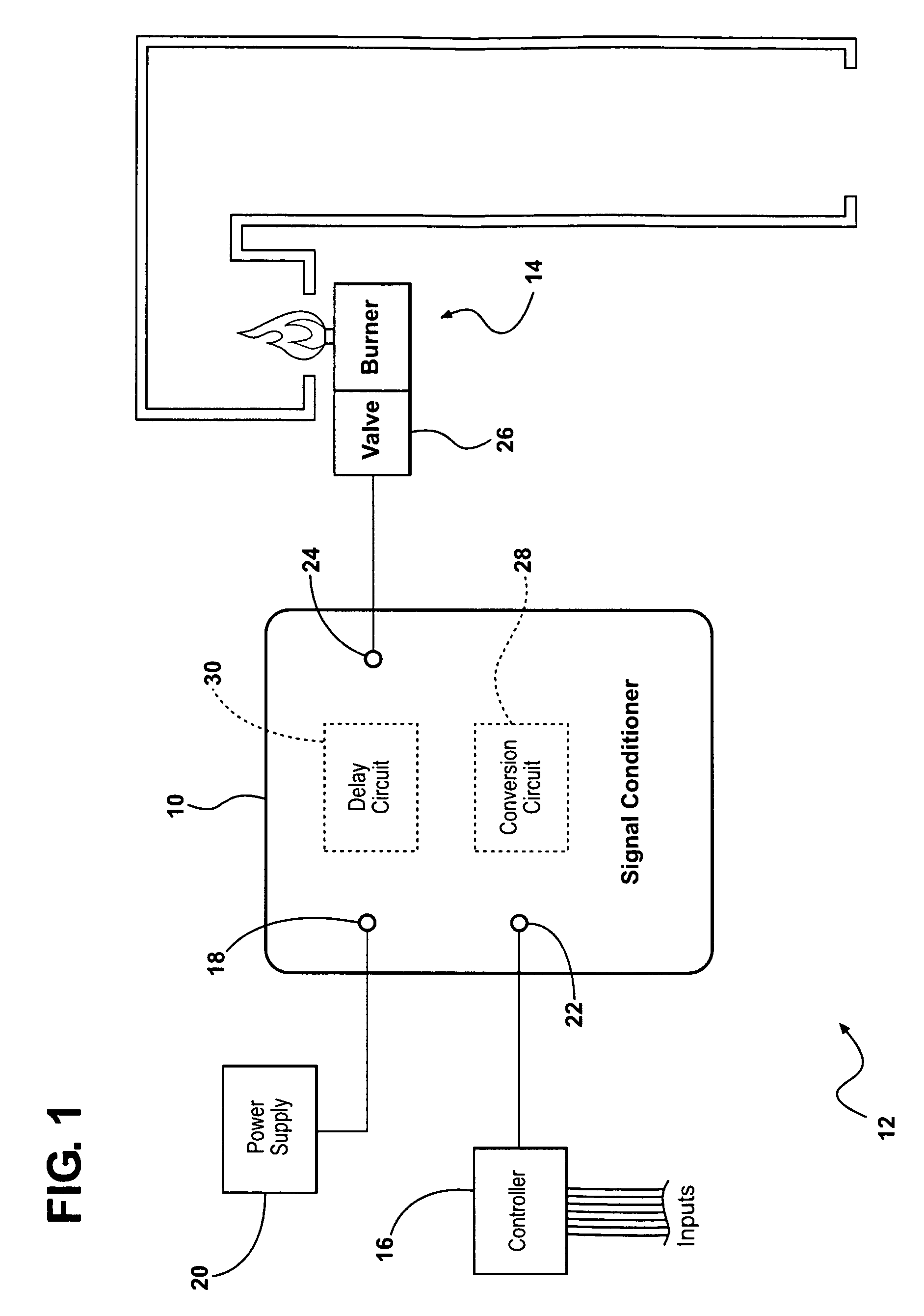
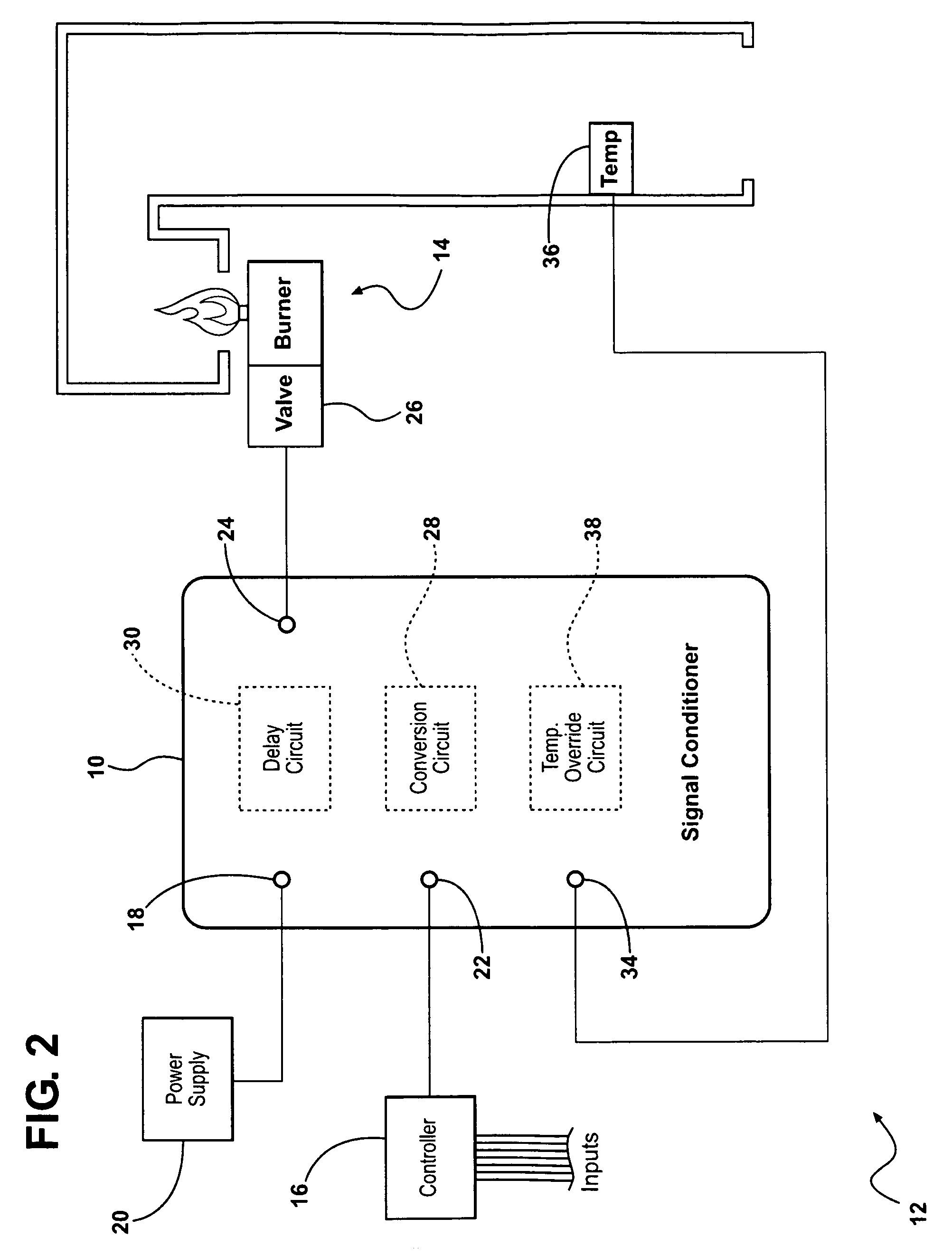
[0017]Referring to the Figures, wherein like numerals indicate like parts throughout the several views, a signal conditioner is shown at 10. In the illustrated embodiments, as shown in FIGS. 1 and 2, the signal conditioner 10 is shown as part of a control system 12 of a burner 14, specifically for heating air, such as in HVAC installations (not shown in detail). However, those skilled in the art realize that the signal conditioner 10 described herein may be implemented in other applications outside of the control of burners.

[0018]The control system 12 of the illustrated embodiment includes a controller 16 for controlling operation of the burner 14. The controller 16 controls operation of the burner 14 based on a variety of inputs known to those skilled in the art including, but not limited to, control signals, temperature setpoint, and temperature sensors. In response to these inputs, the controller 16 produces at least one controller output signal for operating the burner 14. The c...


PUM


Abstract

A signal conditioner for use with a controller and a burner receives an input signal from the controller. A conversion circuit generates a primary output signal corresponding to the input signal to control the burner. The signal conditioner also includes a delay circuit. The delay circuit overrides the primary output signal generated by the conversion circuit and substitutes a delay signal to the burner at a predetermined level for a predetermined time. The signal conditioner may also include a temperature override circuit, which receives a temperature of air from the burner. If the temperature is above or below established limits, the temperature override circuit substitutes a temperature override signal to the burner.

Description

CROSS REFERENCE TO RELATED APPLICATION[0001]This application claims the benefit of provisional patent application No. 61 / 039,642, filed Mar. 26, 2008, which is hereby incorporated by reference.BACKGROUND OF THE INVENTION[0002]1. Field of the Invention[0003]The present invention relates to a signal conditioner. Specifically, the invention relates to a signal conditioner that converts electrical control signals in a burner control system.[0004]2. Description of the Related Art[0005]Automatic controllers, such as microprocessor-based devices, are commonly used to control mechanical devices. Such is the case in modern Heating, Ventilation, and Air Conditioning (HVAC) systems, where a controller is often utilized to control heating devices (e.g., burners), airflow fans, heat exchangers, louvers, and the like. The control of these devices is typically based on a plurality of inputs, such as desired temperature setpoints, temperature sensors, time clocks, and fault monitoring. The controll...

Claims


Application Information

Patent Timeline
Patent Type & Authority Patents(United States)
IPC IPC(8): F23N5/20F23N5/02F23N5/24
CPCF23N5/203F23N5/022F23N5/242F23N2025/14F23N2025/21F23N2027/02F23N2225/14F23N2225/21F23N2227/02
Inventor SCHLACHTER, JOHN JAMESCOOPER, LYNN E.
Owner MAXITROL
Why Eureka
Try Eureka