
Full-automatic oiling machine

A fuel dispenser, fully automatic technology, applied in the direction of engine level, engine components, engine lubrication, etc., can solve the problems of pollution, waste, and high degree of dependence of processed products, and achieve the effect of improving work efficiency, avoiding unexpected situations, and protecting equipment.

Inactive Publication Date: 2016-11-09
和牧电子商务(上海)有限公司
View PDF13 Cites 1 Cited by
  • Summary
  • Abstract
  • Description
  • Claims
  • Application Information

AI Technical Summary

Problems solved by technology

[0004] (1) The degree of dependence on manual operation is high. Because different equipment has different requirements for refueling frequency, some refueling positions need to be refueled every few hours or minutes. Therefore, it is obviously difficult to ensure that it is completely dependent on manual execution. Timely and accurate refueling;
[0005] (2) The control of the amount of refueling is also a point that cannot be accurately guaranteed by manual operation. If there is too much refueling, the excess oil will overflow to the outside, which will not only cause waste, but may also cause pollution to the processed products. If too little refueling, it will affect normal operation of the equipment;
[0006] (3) With the increasing complexity of the current equipment, one piece of equipment even needs to refuel multiple positions at the same time. If the refueling operation is completed only by manpower, not only the refueling efficiency cannot be guaranteed, but also safety hazards may occur due to improper operation. accidents

Method used


Image

  • Full-automatic oiling machine

Examples


Embodiment Construction

[0043] The technical solutions of the present invention will be clearly and completely described below in conjunction with the accompanying drawings. Obviously, the described embodiments are part of the embodiments of the present invention, rather than all of them. Based on the embodiments of the present invention, all other embodiments obtained by those of ordinary skill in the art without creative work shall fall within the protection scope of the present invention.

[0044] In the description of the present invention, it should be noted that the terms "center", "upper", "lower", "left", "right", "vertical", "horizontal", "inner", "outer", etc. The indicated orientation or positional relationship is based on the orientation or positional relationship shown in the drawings, and is only for the convenience of describing the present invention and simplifying the description, rather than indicating or implying that the pointed device or element must have a specific orientation or a ...


PUM


Abstract

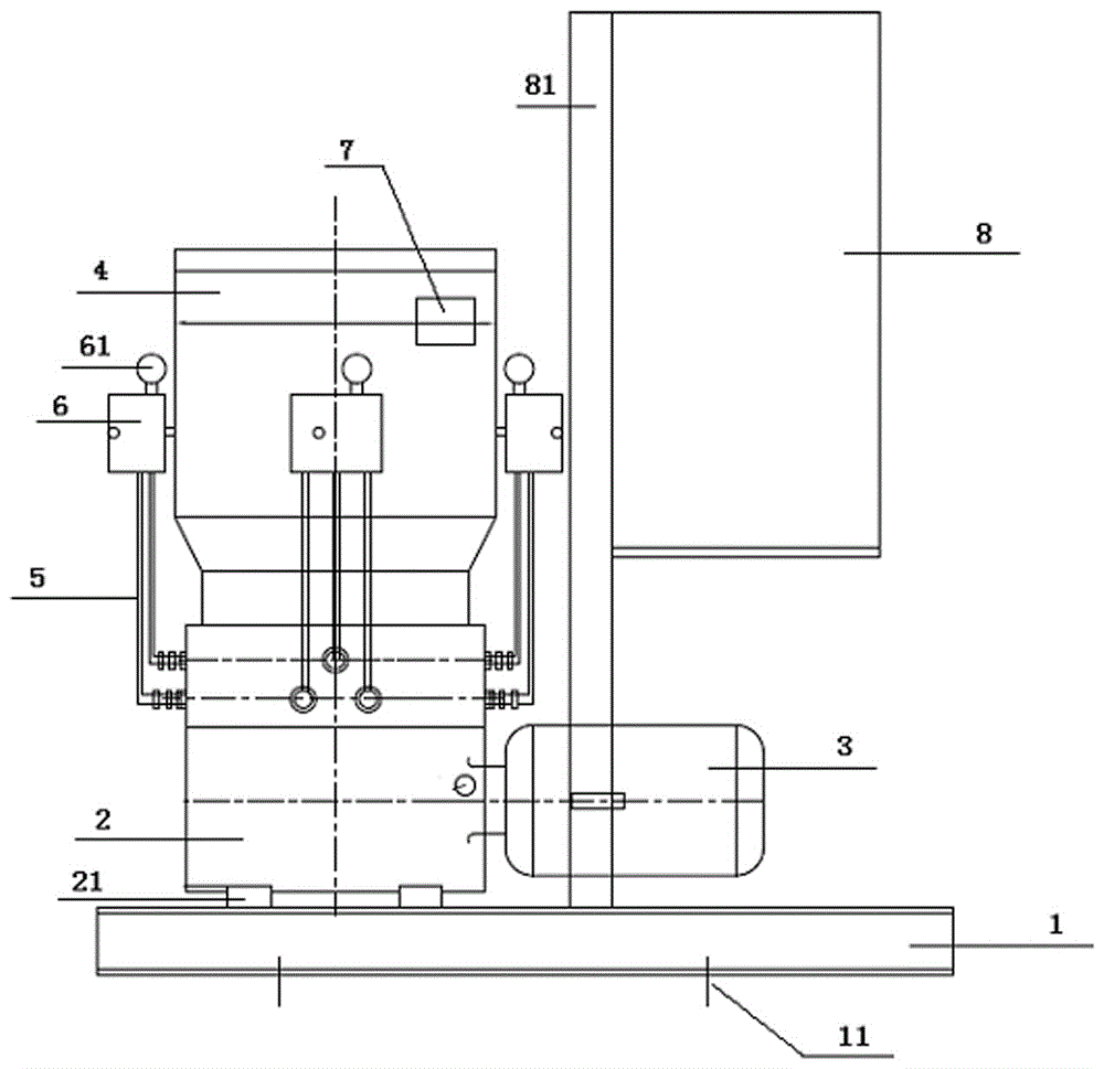
The invention provides a full-automatic oiling machine, comprising a base, an oil pump, an oil pump motor, an oil tank, copper pipes, oil collectors, an oil filling pipe, a high and low oil level system and an electric cabinet, wherein the oil pump motor is connected with the oil pump; the oil tank is arranged above the oil pump, and the oil tank is in through connection with the oil pump; certain ends of the copper pipes are connected with the oil pump, and the other ends of the copper pipes are connected to the oil collectors; at least three copper pipes are connected with one oil collector at the same time; one end of the oil filling pipe is connected with one oil collector, and the other end of the oil filling pipe extends to a device to be oiled; each oil collector is also provided with an oil control switch; the high and low oil level system is arranged on the oil tank; the electric cabinet is connected with the high and low oil level system and the oil pump motor. By a brand new design of the full-automatic oiling machine, not only are the parts and combination thereof of the oiling machine changed, but more importantly, the working mode and the control form of the oiling machine are also changed; therefore, unmanned operation and precision are realized.

Description

Technical field [0001] The invention relates to the field of mechanical design and manufacturing and the field of electrical control and induction, in particular to a fully automatic fuel dispenser. Background technique [0002] The fuel dispenser in the prior art is generally an ordinary pneumatic device, which blows oil through the oil pipe into the place where the equipment needs to be refueled by blowing air that controls the compression ratio. When the pneumatic switch is turned on, the fuel is started, and when the pneumatic switch is turned off, the fuel is stopped. It can be seen that the existing oil dispensers generally rely on manual operation, and the operator controls the air compressor in real time to push the lubricating grease to the position to be refueled to complete the refueling operation. [0003] At present, in the specific application process of the existing technology, the fuel dispenser has the following drawbacks, including: [0004] (1) The degree of depe...

Claims


Application Information

Patent Timeline
IPC IPC(8): F16N7/38F16N29/04
CPCF16N7/38F16N29/04F16N2250/18F16N2260/04
Inventor 刘小六杨晨
Owner 和牧电子商务(上海)有限公司
Learn More