Master cylinder device

a master cylinder and cylinder body technology, applied in the direction of rotary clutches, braking systems, fluid couplings, etc., can solve the problems of deterioration of operational feeling and deterioration of operation feeling, so as to enhance the utility of the master cylinder device, the effect of reducing the operation amount of the brake operation member in the brake operation and reducing the operation difficulty

Inactive Publication Date: 2015-05-26
TOYOTA JIDOSHA KK
View PDF9 Cites 2 Cited by
  • Summary
  • Abstract
  • Description
  • Claims
  • Application Information

AI Technical Summary

Benefits of technology

[0004]Even when the above mentioned cylinder device is actuated so as to pressurize the brake fluid depending only on the operation force, the stroke simulator is put in a state in which it can function. Accordingly, the movement of the operation member owing to the stroke simulator is allowed, and an operation amount of the brake operation member in a brake operation becomes comparatively large. Therefore, operational feeling in a brake operation is deteriorated. Such a deterioration of operational feeling is one example of problems which a master cylinder device with a stroke simulator has, and the master cylinder device has a variety of problems other than it. Therefore, it is possible to carry out a variety of improvements, thereby enhancing utility of the master cylinder device. This invention has been made in the light of such a fact, and it is therefore an object of the invention to provide a master cylinder device with enhanced utility.
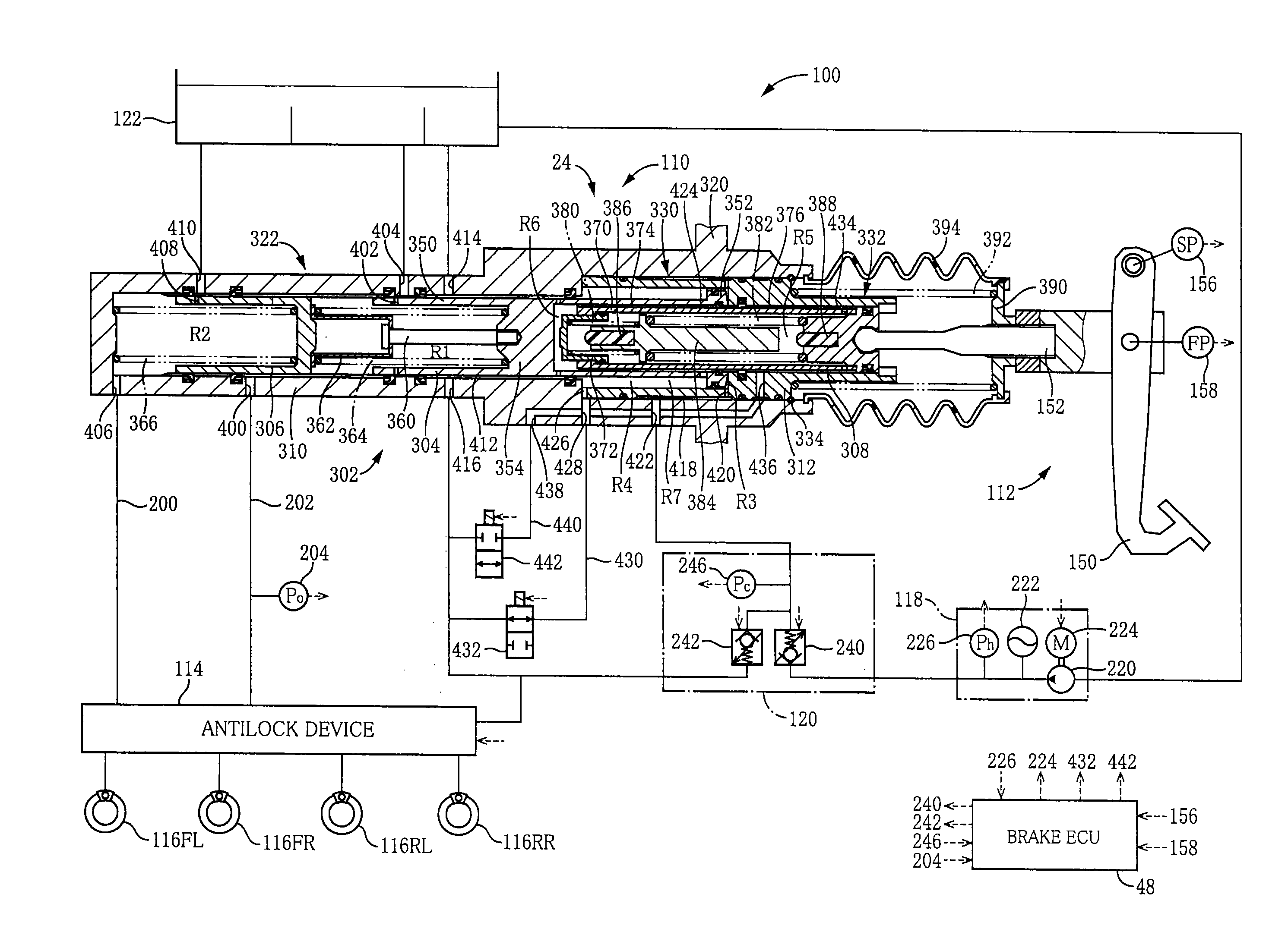
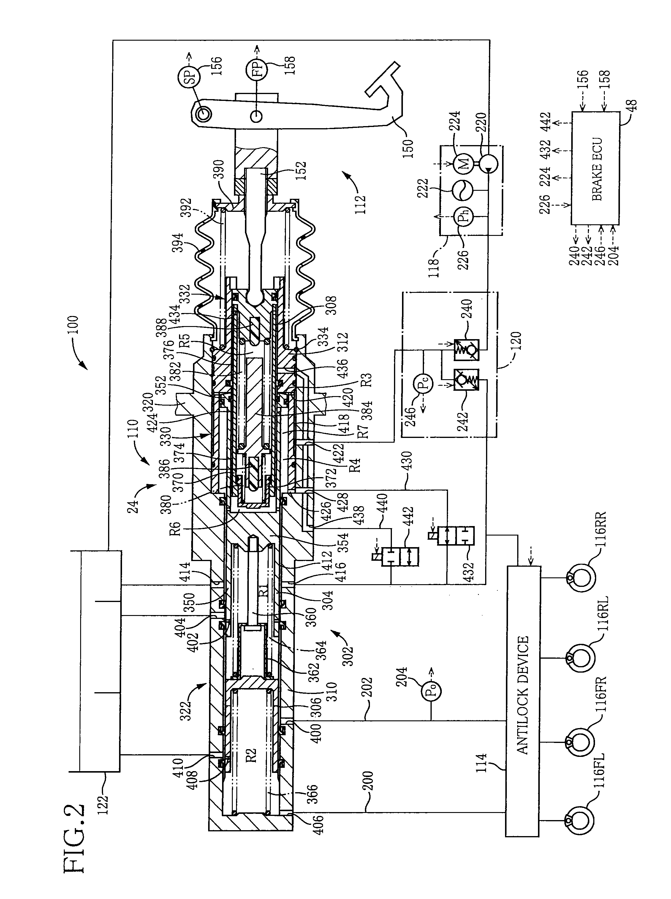
[0005]To achieve the object, a master cylinder device according to the present invention includes: (A) a pressurizing piston which includes a main body portion in front of which there is defined a pressurizing chamber for pressurizing a brake fluid, and a flange portion formed around an outer circumference of the main body portion, and which is disposed such that, in the rear of the flange portion, there is defined an input chamber into which a brake fluid is introduced from a high pressure source, and, in front of the flange portion, there is defined an opposing chamber filled with a brake fluid and opposing to the input chamber; (B) an input piston which can shrink by operating an operation member, and which is disposed such that, in front of the input piston and between the input piston and the pressurizing piston, there is defined an inter-piston chamber; and (C) a reaction force generating mechanism which generates an elastic reaction force against the shrink of the input piston. Furthermore, the master cylinder device includes a low-pressure-source communicating device for making the opposing chamber and the inter-piston chamber communicate with a low pressure source so as to allow the input piston to come into abutting contact with the pressurizing piston, and an input-piston-shrink prohibiting mechanism for prohibiting the shrink of the input piston.
[0006]In the master cylinder device according to the present invention, when the abutting contact of the input piston with the pressurizing piston is allowed by the low-pressure-source communicating device, an operation force applied to the operation member is transmitted to the pressurizing piston. Moreover, when the shrink of the input piston is prohibited by the input-piston-shrink prohibiting mechanism, the operation force can be transmitted to the pressurizing piston in a state in which a stroke simulator does not function and movement of the operation member owing to the stroke simulator is prohibited. Whereby, the brake fluid in the pressurizing chamber can be pressurized depending on the operation force. Therefore, the brake fluid in the pressurizing chamber can be pressurized in a comparatively small operation amount, thus operational feeling becomes favorable. This can enhance utility of the master cylinder device.(B) Forms of Claimable Invention

Problems solved by technology

Therefore, operational feeling in a brake operation is deteriorated.
Such a deterioration of operational feeling is one example of problems which a master cylinder device with a stroke simulator has, and the master cylinder device has a variety of problems other than it.

Method used


Image

  • Master cylinder device
  • Master cylinder device
  • Master cylinder device

Examples


first embodiment

Structure of Vehicle

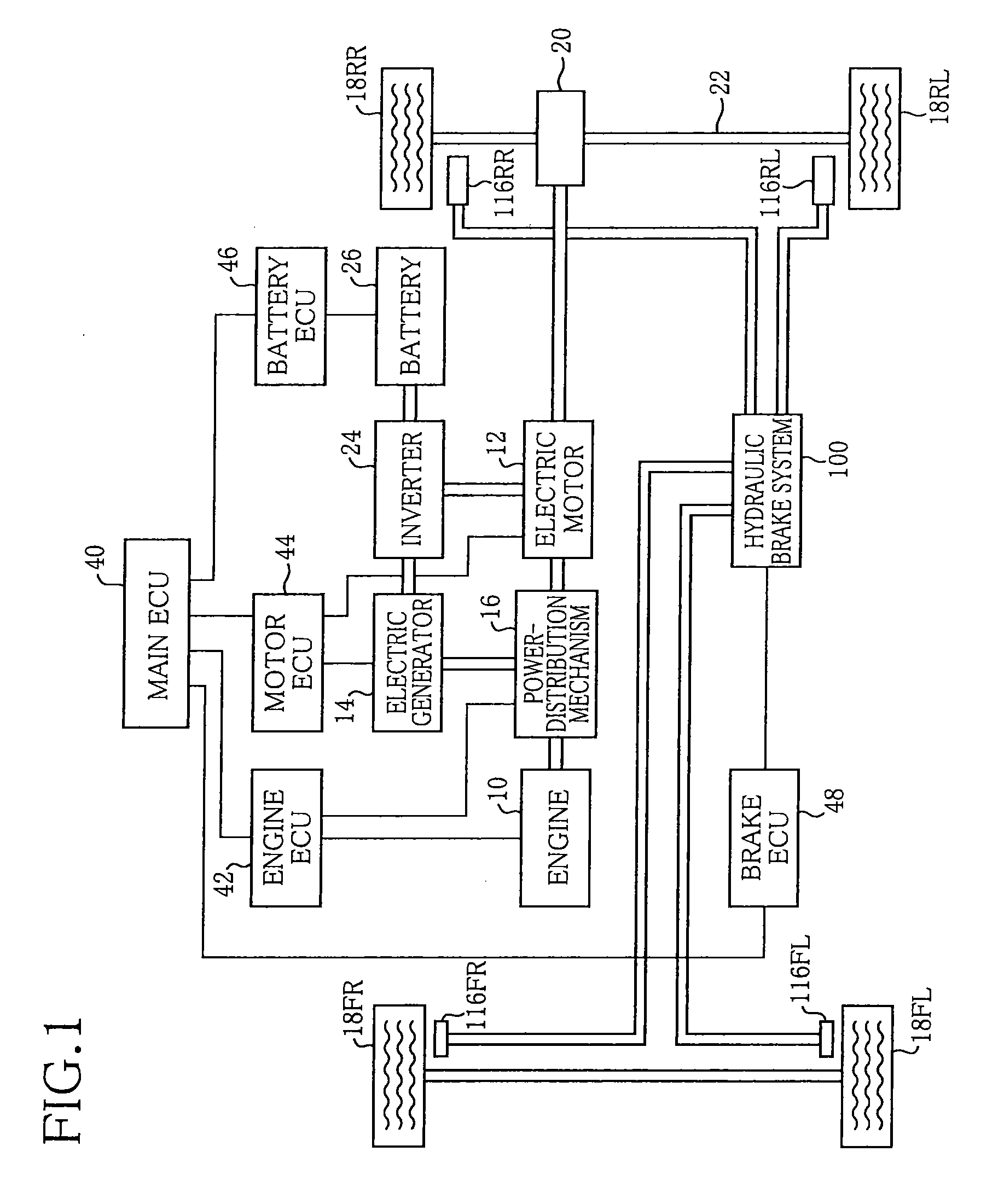
[0073]FIG. 1 schematically illustrates a drive system and a brake system of a hybrid vehicle which is equipped with a master cylinder device of a first embodiment. The vehicle is equipped with an engine 10 and an electric motor 12 as sources of power, and also equipped with an electric generator 14 which generates electricity by an output power of the engine 10. The engine 10, the electric motor 12, and the electric generator 14 are connected to one another via a power-distribution mechanism 16. By controlling the power-distribution mechanism 16, the power of the engine 10 can be divided into a power for driving the electric generator 14 and a power for rotating drive wheels among four wheels 18, and a power of the electric motor 12 can be transmitted to the drive wheels. In other words, the power-distribution mechanism 16 functions as a speed-change mechanism with respect to a driving power which is transmitted to the drive wheels via a speed reducer 20 and a dr...

modified embodiment

[0113]FIG. 4 illustrates the hydraulic brake system 100 having a master cylinder device 500 of the modified embodiment substituting for the master cylinder device 110 of the first embodiment. Generally speaking, the master cylinder device 500 has the same structure as the master cylinder device 110 of the first embodiment except for having a mechanical open / close valve 502 substituting for the electromagnetic open / close valve 442 provided in the middle of the external communication passage 440 of the master cylinder device 110 of the first embodiment. In the following explanation, centering on the open / close valve 502, only structure and actuation different from the master cylinder device 110 of the first embodiment are explained.

[0114]The open / close valve 502 is provided in the middle of the external communication passage 440. FIG. 5 is a cross sectional view of the open / close valve 502. The open / close valve 502 includes a housing 510 which is a casing, and a valve body member 512 ...

second embodiment

[0123]FIG. 6 illustrates the hydraulic brake system 100 having a master cylinder device 600 of the second embodiment substituting for the master cylinder device 110 of the first embodiment. Generally speaking, the master cylinder device 600 has the same structure as the master cylinder device 110 of the first embodiment. In the following explanation, in the interest of brief description, only structure and actuation different from the master cylinder device 110 of the first embodiment are explained

[0124]An input piston 602 of the master cylinder device 600 has a structure in which the springs etc. provided in the input piston 308 of the master cylinder device 110 of the first embodiment are removed. Additionally, in the master cylinder device 600, on the external communication passage 440, there are provided an electromagnetic open / close valve 606 being a normally close valve and an electromagnetic open / close valve 608 being a normally open valve. In the master cylinder device 600, ...


PUM


Abstract

A master cylinder device includes: a first pressurizing piston including a main body portion which defines a first pressurizing chamber for pressurizing a brake fluid, and a flange portion which is formed around an outer circumference of the main body portion and in front of which there is defined an opposing chamber; and an input piston which can be shrunk by operating a brake pedal. The master cylinder device further includes an electromagnetic open / close valve for making the opposing chamber and the inter-piston chamber communicate with a reservoir, and an electromagnetic open / close valve for prohibiting the shrink of the input piston. The master cylinder device with such a structure allows a pressurization of the brake fluid depending on an operation force in a state in which the shrink of the input piston is prohibited.

Description

TECHNICAL FIELD[0001]The present invention relates to a master cylinder device for pressurizing a brake fluid and supplying the brake fluid to a brake device provided in a wheel.BACKGROUND ART[0002]Recently, in a hydraulic brake system of a vehicle, for example, as described in the following Patent Document 1, a master cylinder device that is normally actuated so as to pressurize a brake fluid depending only on a pressure of the highly pressured brake fluid which is introduced from a high pressure source, is employed. The master cylinder device commonly has a stroke simulator. According to an operation force applied to an operation member by a driver, the stroke simulator allows a movement of the operation member while generating an operation reaction force against the operation force. Therefore, even when the brake fluid is not pressurized depending on the operation force, the driver can realistically feel the operation reaction force while moving the operation member by a driver's...

Claims


Application Information

Patent Timeline
Patent Type & Authority Patents(United States)
IPC IPC(8): B60T13/14B60T8/40
CPCB60T13/144B60T8/4077
Inventor ISONO, HIROSHI
Owner TOYOTA JIDOSHA KK
Why Eureka
Try Eureka