Printer with pair of tape roll guide members having a recessed part for housing a pressing roller

a technology of pressing roller and guide member, which is applied in the field of printing machines, can solve the problems of unstable feeding of print-receiving tape, affecting printing, and slack in the print-receiving tape, and achieves the effect of wide adjustable space range and increased strength of guide members

Active Publication Date: 2015-05-26
BROTHER KOGYO KK
View PDF8 Cites 1 Cited by
  • Summary
  • Abstract
  • Description
  • Claims
  • Application Information

AI Technical Summary

Benefits of technology

[0009]It is therefore an object of the present disclosure to provide a printer capable of supporting a roll with diverse tape widths by guide members while stabilizing the feeding of the print-receiving tape by a pressing roller.
[0012]The printer of the present disclosure comprises a pressing roller rotatably provided on the cover. This pressing roller contacts the print-receiving tape fed out from the roll near the feed-out position, making it possible to impart tension to the print-receiving tape and suppress the looseness when the feeding is stopped. With this arrangement, the feeding of the tape is stabilized, making it possible to suppress a printing disturbance.
[0013]On the other hand, the printer comprises a pair of guide members in the roll storage part. These guide members advance and retreat in tandem in the width direction of the roll with respect to a reference position, making it possible to adjust the space in accordance with a roll with diverse tape widths.
[0015]Hence, according to the present disclosure, each of the guide members comprises a recessed part at a position corresponding to the pressing roller. This recessed part houses at least a part of the pressing roller, thereby making it possible to secure a wide adjustable range of the space between the guide members, even in a case where a relatively large roller width is set. Accordingly, it is possible to support a roll with diverse tape widths by the guide members while stabilizing the feeding of the print-receiving tape by the pressing roller.
[0016]Further, by thus providing a recessed part on each guide member, it is possible to extend the guide members up to the downstream side in the tape transport direction than the position where the pressing roller is provided while avoiding contact with the pressing roller. With this arrangement, it is possible to support the guide members near the tape feed-out position, thereby making it possible to increase the strength of the guide members. As a result, it is possible to stabilize and guide the print-receiving tape fed out from the roll.

Problems solved by technology

Nevertheless, according to the printer of the prior art, the print-receiving tape is repeatedly fed and stopped, thereby sometimes producing slack in the print-receiving tape near the feed-out position when the feeding is stopped due to the vibration of the apparatus itself, external impact, or the like.
In such a case, slackened winding may occur in the roll, making the feeding of the print-receiving tape become unstable when feeding is resumed, triggering a printing disturbance.
However, if the roller width of the pressing roller is set relatively small so that the pressing roller is not contacted when the space between the guide members is narrowed, the pressing roller cannot adequately press the print-receiving tape, resulting in the possibility that the feeding of the tape will become unstable.
On the other hand, while the feeding of the tape stabilizes when a large roller width is set, the space between the guide members cannot be set smaller than the roller width, thereby significantly restricting the adjustable range of the space between the guide members, making it no longer possible to support a roll with diverse tape widths.
In such a case, slackened winding may occur in the roll, making the feeding of the print-receiving tape become unstable when feeding is resumed, triggering a printing disturbance.
In such a configuration, if the roller width of the pressing roller is set relatively small so that the pressing roller is not contacted when the space between the guide members is narrowed, the pressing roller cannot adequately press the print-receiving tape, resulting in the possibility that the feeding of the tape will become unstable.
On the other hand, while the feeding of the tape stabilizes when a large roller width is set, the space between the guide members cannot be set smaller than the roller width, thereby significantly restricting the adjustable range of the space between the guide members, making it no longer possible to support a roll with diverse tape widths.

Method used


Image

  • Printer with pair of tape roll guide members having a recessed part for housing a pressing roller
  • Printer with pair of tape roll guide members having a recessed part for housing a pressing roller
  • Printer with pair of tape roll guide members having a recessed part for housing a pressing roller

Examples


Embodiment Construction

[0029]The following describes an embodiment of the present disclosure with reference to accompanying drawings.

General Outer Appearance Configuration

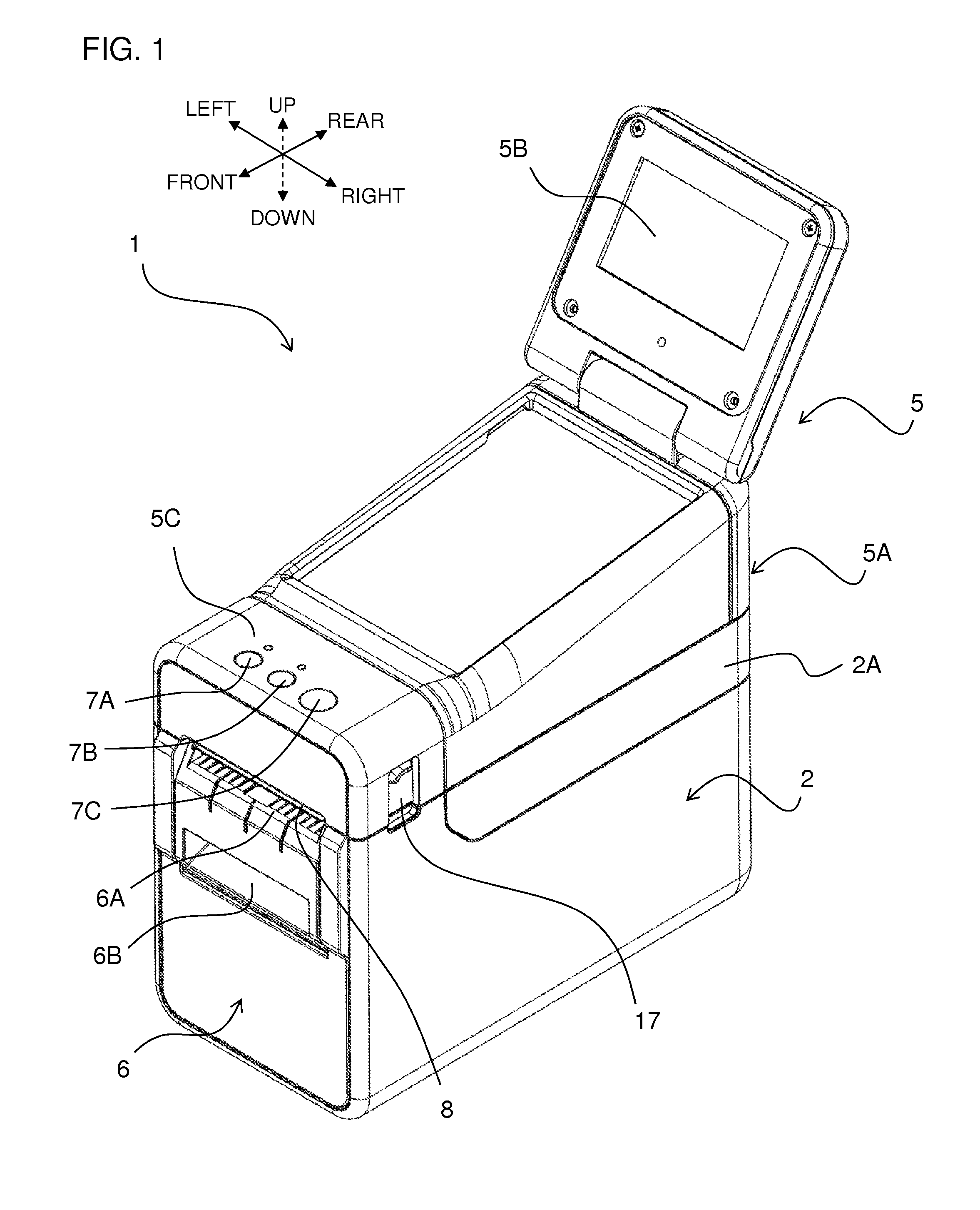
[0030]First, the general outer appearance configuration of the label producing apparatus 1 of this embodiment will be described using FIG. 1. Note that the front-rear direction, left-right direction, and up-down direction in the descriptions below indicate the directions of the arrows suitably shown in each figure, such as FIG. 1.

[0031]In FIG. 1, the label producing apparatus 1 comprises a housing 2 comprising a front panel 6, and an upper cover unit 5. The housing 2 and the upper cover unit 5 are made of resin, for example. The upper cover unit 5 comprises a touch panel part 5A, a substantially rectangular-shaped liquid crystal panel part 5B, and an operation button part 5C.

[0032]The upper cover unit 5 is pivotably connected to the housing 2 at the rearward end part via a rotating shaft part 2a (refer to FIG. 4 described later), forming...


PUM


Abstract

This disclosure discloses a printer comprising a roll storage part, a feeder, a printing head, a pair of guide members, a guide driving mechanism, a cover, a pressing roller, and a recessed part. The printing head is configured to perform desired printing on the print-receiving tape fed by a feeder. The pair of guide members are configured to determine a width-direction position of the print-receiving tape while sandwiching the stored roll. The guide driving mechanism is configured to make the pair of guide members move close to and away from each other by advancing and retreating in tandem in a width direction of the roll. The pressing roller is configured to contact the print-receiving tape near a feed-out position. The recessed part is configured to house at least a part of the pressing roller, provided to each position of the pair of guide members.

Description

CROSS-REFERENCE TO RELATED APPLICATION[0001]The present application claims priority from Japanese Patent Application No. 2013-45766, which was filed on Mar. 7, 2013, the disclosure of which is incorporated herein by reference in its entirety.BACKGROUND[0002]1. Field[0003]The present disclosure relates to a printer that produces a print label by performing desired printing on a print-receiving tape.[0004]2. Description of the Related Art[0005]There are known printers which produce print labels by performing desired printing on a print-receiving tape. Such a printer stores a roll around which is wound the print-receiving tape into a roll shape in a roll storage part, and performs desired printing on the print-receiving tape by printing means while feeding out the print-receiving tape from the roll by feeding means. The print-receiving tape on which printing has been thus performed is then discharged to the outside of the housing and, in such a state, the roll side is cut by cutting me...

Claims


Application Information

Patent Timeline
Patent Type & Authority Patents(United States)
IPC IPC(8): B41J15/04B41J15/16B65H16/08
CPCB41J15/042B41J15/16B65H16/08B41J15/046
Inventor OHNISHI, HIROKIHOKAZONO, TAKAMINEUCHINO, KUMIKOJO, HIDENORINAGASHIMA, YUKISEO, KEIJI
Owner BROTHER KOGYO KK
Why Eureka
Try Eureka