
Slip ring apparatus for electric rotating machine

Active Publication Date: 2015-11-19
MITSUBISHI ELECTRIC CORP
View PDF3 Cites 0 Cited by
  • Summary
  • Abstract
  • Description
  • Claims
  • Application Information

AI Technical Summary

Benefits of technology

The invention is a slip ring apparatus that prevents the leads of an electric rotating machine from displacement or deformation during insert molding. A restricting member helps maintain tension on the lead portions in the mold, ensuring proper placement and preventing issues during the manufacturing process. Overall, the slip ring apparatus improves the reliability and efficiency of the molding process.

Problems solved by technology

In the case that the deformation absorbing portion is a bend portion, there is a possibility that the thickness of the bend portion that has been deformed does not fall within the range of the thickness of the connecting portion because the connecting portion, in which the lead is buried, does not have a sufficient radial thickness size.
In the case that the deformation absorbing portion is a cut-out portion or a through-hole portion, the thickness of the lead does not increase, but it is possible that the lead may not fit into the insulating member because of deformation.
In either case, there is a risk that the lead may be exposed outside the insulating member depending on the degree of deformation of the deformation absorbing portion.
Consequently, there is a possibility that the lead cannot be able to withstand external forces and may result in breakage.
In the slip ring apparatus, it is impossible to confirm in what shape the lead is accommodated in the molded body.
For these reasons, it is undesirable, from the viewpoint of reliability, to lower the strength of the lead by providing the deformation absorbing portion in the slip ring apparatus.
However, strictly speaking, the technique can restrict the position of the lead only in radial directions.

Method used


Image

  • Slip ring apparatus for electric rotating machine
  • Slip ring apparatus for electric rotating machine
  • Slip ring apparatus for electric rotating machine

Examples


first embodiment

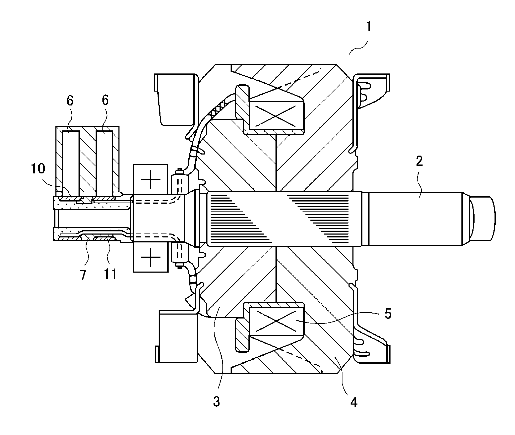
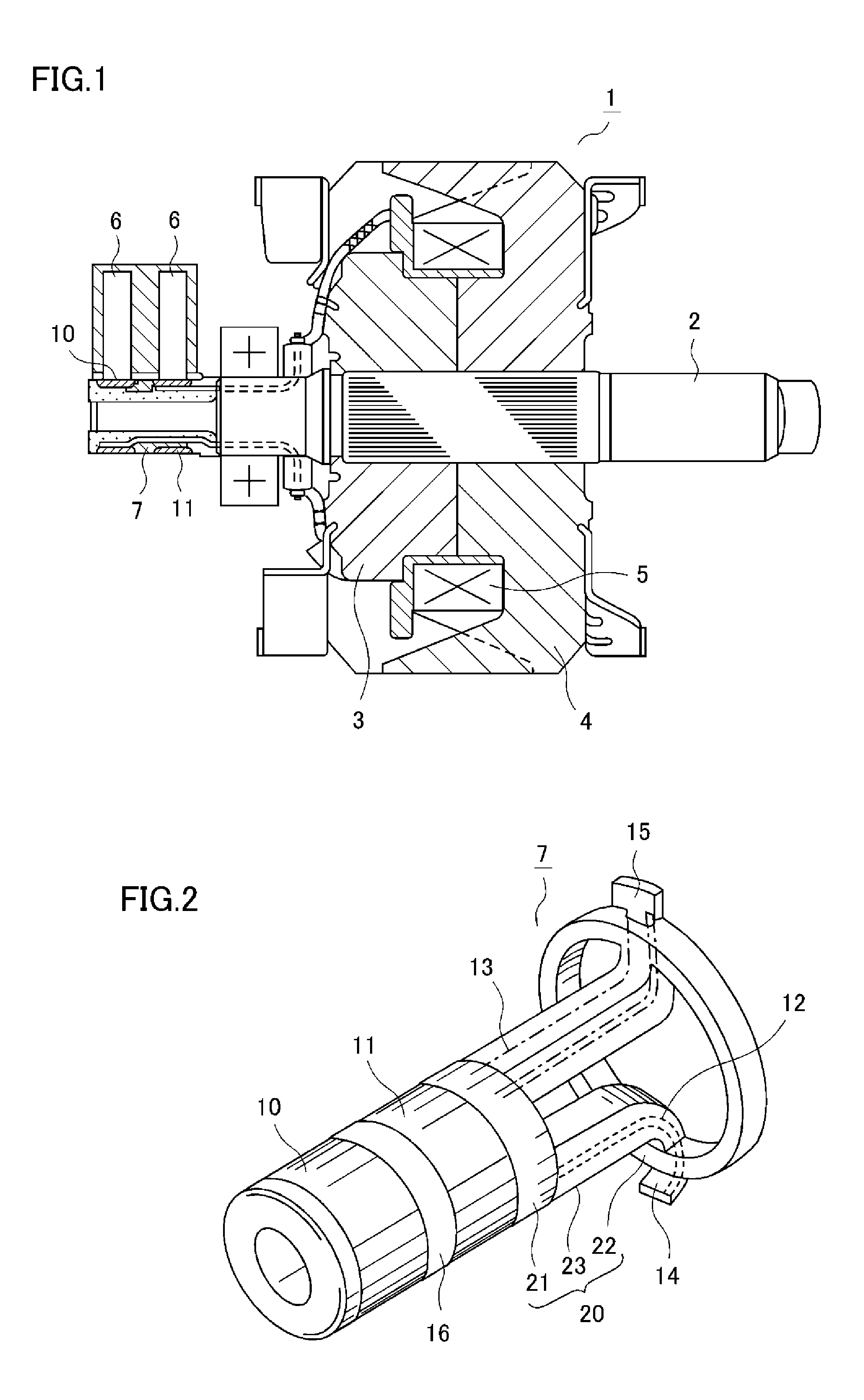
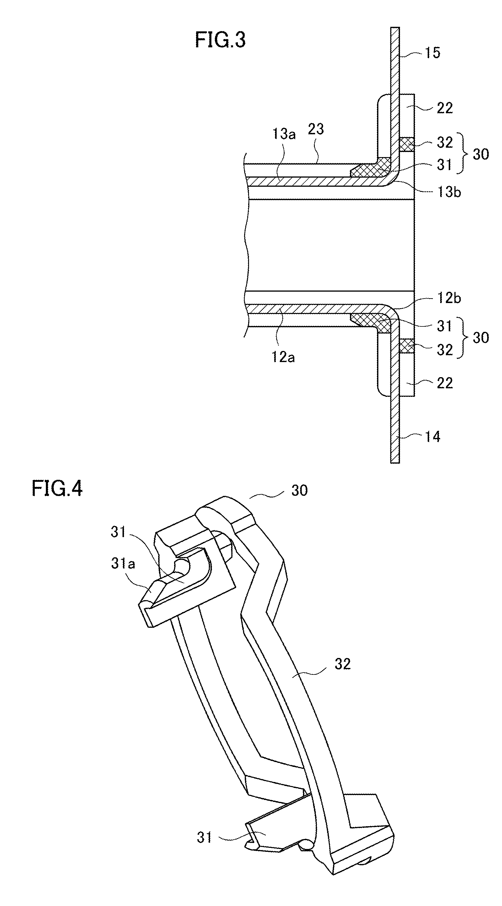
[0025]Hereinbelow, a slip ring apparatus, according to a first embodiment of the invention, of an alternator for the vehicle will be described with reference to the drawings. FIG. 1 is a cross-sectional view along an axis line direction showing a rotor of an alternator for the vehicle provided with the slip ring apparatus according to the first embodiment of the invention. FIGS. 2 and 3 are a perspective view showing the slip ring apparatus according to the first embodiment of the invention, and an enlarged cross-sectional view showing a primary portion thereof, respectively. It should be noted that, in the drawings, the same or corresponding component parts are designated by the same reference signs.

[0026]A rotor 1 of an alternator for the vehicle (hereinafter referring to as “alternator”) is provided inside a stator (not shown) fixed to an inner wall of a case (not shown) and is fixed to a shaft 2. The rotor 1 has a pair of claw magnetic poles 3 and 4 opposed to each other, and a ...

second embodiment

[0044]In a second embodiment of the invention, a modified example of the restricting member 30, which has been described in the foregoing first embodiment, will be described with reference to FIGS. 7 and 8. The overall configuration of the slip ring apparatus according to this second embodiment is substantially the same as that described in the foregoing first embodiment. Therefore, referring again to FIG. 2, the detailed descriptions thereof are omitted.

[0045]As shown in FIG. 7, each of lead support portions 33 of a restricting member 30A according to the second embodiment has a recessed portion that surrounds three faces of the bent lead portion 12b (13b) each facing a different direction, including a radially outward face thereof. This makes it possible to retain the bent lead portion 12b (13b) more reliably.

[0046]Each of the lead support portions 33 has a first tapered portion 33a being a tip end portion to be inserted into a mold and being tapered toward the insertion direction...


PUM


Abstract

A restricting member is provided that is in contact with respective bent lead portions of a long-sized lead and a short-sized lead and imparts a tension to linear lead portions thereof in a mold for insert molding. The restricting member reliably prevents the leads from displacement and deformation resulting from the pressure of the resin at the time of insert molding, and allows the long-sized lead and the short-sized lead to be disposed at proper positions in a molded body.

Description

BACKGROUND OF THE INVENTION[0001]1. Field of the Invention[0002]The present invention relates to a slip ring apparatus for an electric rotating machine such as an alternator for the vehicle.[0003]2. Description of the Background Art[0004]An electric rotating machine, such as an alternator for the vehicle, uses a slip ring apparatus in which a pair of slip rings each having a lead joined thereto are integrally formed by a molded body made of an insulating resin. Conventional slip ring apparatuses sometimes cause defects due to displacement or deformation of the leads, which result from the pressure of the resin during insert molding, and a structure which prevents these defects has been required.[0005]For example, Patent Document 1 proposes, as a configuration for absorbing the deformation of the leads and allowing the lead to be disposed at a predetermined position, provision of a deformation absorbing portion in the lead within a connecting portion that connects a slip ring support...

Claims


Application Information

Patent Timeline
IPC IPC(8): H02K13/02H02K3/38
CPCH02K3/38H02K13/02H01R39/08H01R13/5845H01R39/16
Inventor SAKAGUCHI, MASAYUKISHIMIZU, SHINTARO
Owner MITSUBISHI ELECTRIC CORP
Learn More