
System and method for diagnostics of a grid based digitizer

a grid-based digitizer and diagnostic system technology, applied in the field can solve the problems of limiting their mobility, affecting the diagnostic accuracy of touch sensitive digitizers, and affecting the diagnostic accuracy of touch sensitive digitizers, and achieve the effect of cost saving

Active Publication Date: 2015-05-26
MICROSOFT TECH LICENSING LLC
View PDF17 Cites 10 Cited by
  • Summary
  • Abstract
  • Description
  • Claims
  • Application Information

AI Technical Summary

Benefits of technology

[0009]An aspect of some embodiments of the invention is the provision of cost efficient systems and methods for monitoring and testing touch sensitive digitizers while assembled. According to some embodiments of the present invention, there is provided a method where monitoring and testing of the touch devices is performed autonomously, e.g. self-operated by the digitizer and does not require dedicated hardware, external testing tools and / or user intervention.

Problems solved by technology

These new devices are usually not connected to standard keyboards, mice or like input devices, which are deemed to limit their mobility.
Touch detection accuracy may change and / or touch sensitive digitizers may malfunction over time due to a number of system and environmental reasons, such as due to handling and dropping of the device.
Such evaluation is typically both costly and time inefficient.

Method used


Image

  • System and method for diagnostics of a grid based digitizer
  • System and method for diagnostics of a grid based digitizer
  • System and method for diagnostics of a grid based digitizer

Examples


Embodiment Construction

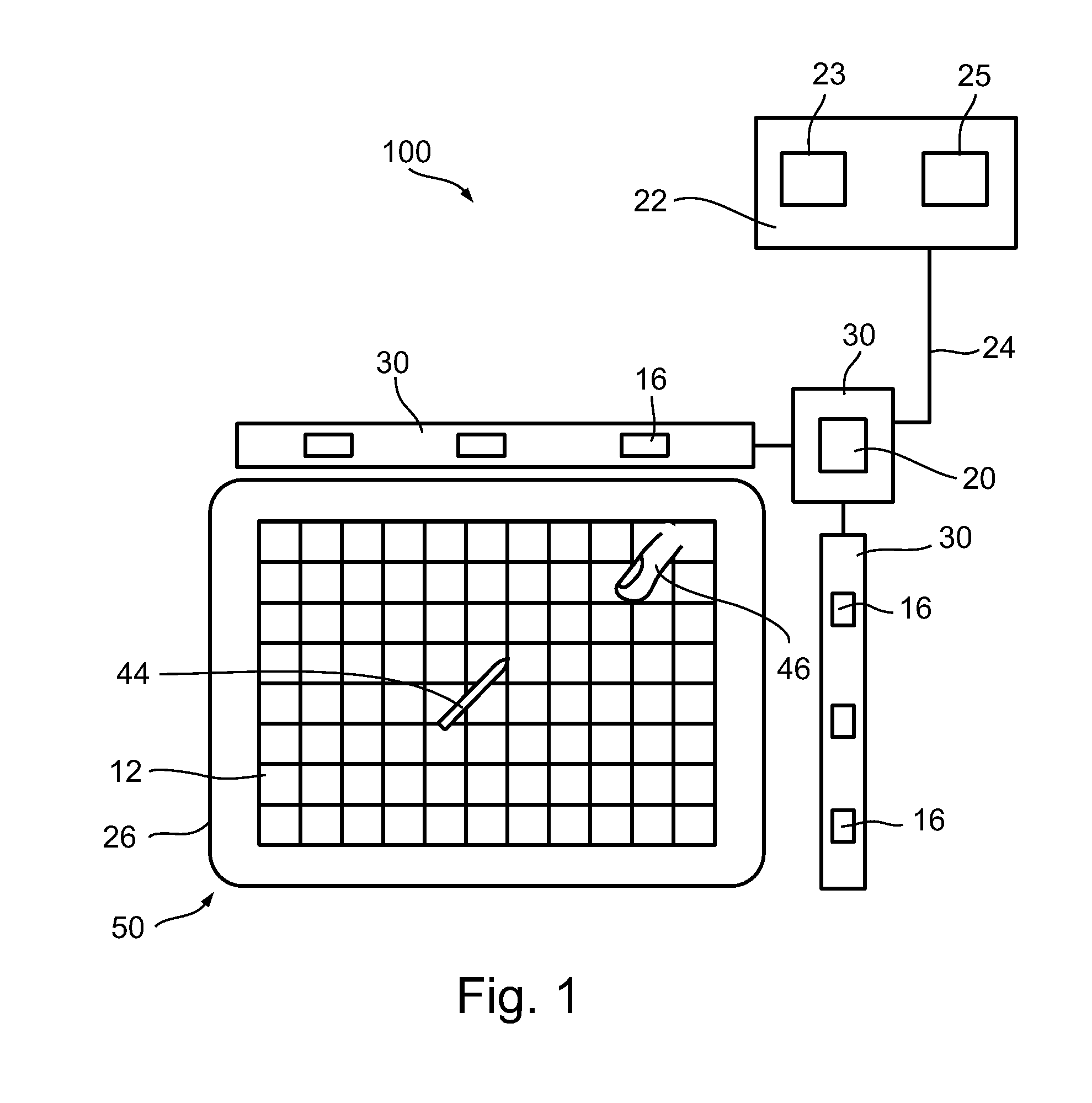
[0086]The present invention relates to a digitizer, and more particularly to diagnostics of a digitizer. A defect in one of the sensor's conductors and / or coil connectivity may result in false detected position of an object and therefore reduces the system's accuracy. A need arises for a self-diagnostic method adapted to diagnose problems in the digitizer system, for example by measuring whether there are defects in the sensor's conductors.

[0087]An aspect of some embodiments of the present invention is the provision of methods for a grid based digitizer to autonomously perform diagnostics, monitoring and / or determining of its operative properties without requiring user intervention, e.g. interaction with the digitizer or engagement with an external diagnostic device. According to some embodiments of the present invention, self-monitoring and / or self-determination of the operative properties of the digitizer is initiated in response to user command, at pre-defined intervals, and / or i...


PUM


Abstract

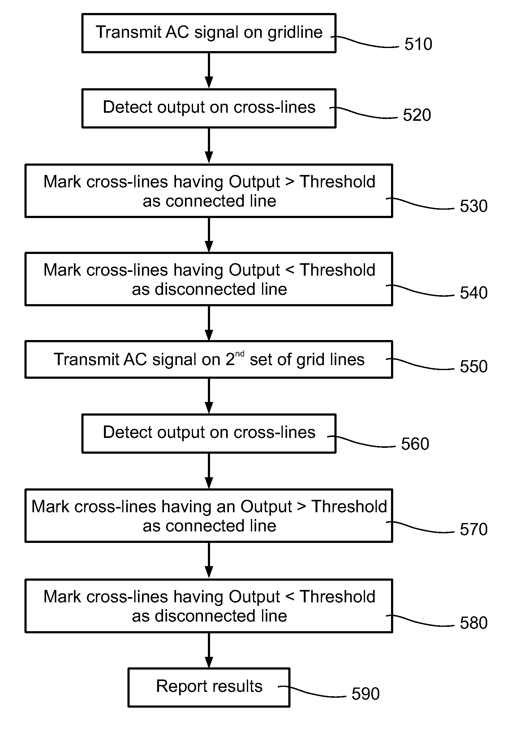
A method for testing a digitizer to determine an operative property of the digitizer, wherein the digitizer includes a sensor grid, comprises providing an input signal on a first portion of the sensor grid, detecting at least one output signal in a second portion of the sensor grid responsive to the input signal in the first portion, and determining at least one operative property of the sensor based on the at least one output signal, wherein at least the transmitting, detecting and determining is performed autonomously by the digitizer.

Description

RELATED APPLICATIONS[0001]The present application claims the benefit under section 35 U.S.C. §119(e) of U.S. Provisional Application No. 60 / 935,115 filed on Jul. 26, 2007 and of U.S. Provisional Application No. 61 / 006,272 filed on Jan. 4, 2008 both of which are incorporated herein by reference in their entirety.FIELD OF THE INVENTION[0002]The present invention relates to a touch sensitive digitizer, and more particularly to diagnostics of a touch sensitive digitizer.BACKGROUND OF THE INVENTION[0003]Touch technologies are commonly used as input devices for a variety of products. The usage of touch devices of various kinds is growing sharply due to the emergence of new mobile devices such as Personal Digital Assistants (PDA), tablet PCs and wireless Flat Panel Display (FPD) screen displays. These new devices are usually not connected to standard keyboards, mice or like input devices, which are deemed to limit their mobility. Instead there is a tendency to use touch sensitive digitizer...

Claims


Application Information

Patent Timeline
Patent Type & Authority Patents(United States)
IPC IPC(8): G06F3/041G09G3/20G06F3/044
CPCG06F3/041G06F3/0418G06F3/044G06F2203/04111G06F3/04166G06F3/0445G06F3/0446G06F11/2221
Inventor PERSKI, HAIMMOORE, JONATHANSHMULEVICH, ROMANTAMIR, ORANNARKISS, NIV
Owner MICROSOFT TECH LICENSING LLC
Learn More